1KR-FE ENGINE CONTROL SFI SYSTEM P244B00 Particulate Filter Differential Pressure Too High Bank 1
DESCRIPTION
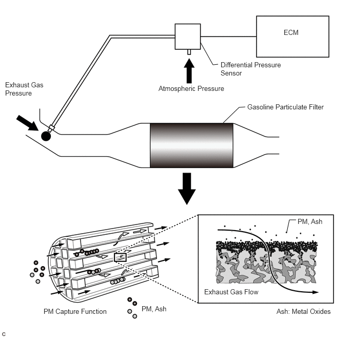
The GPF (Gasoline Particulate Filter) system is an exhaust purification system for processing the PM (Particulate Matter) discharged from the engine. The GPF catalyst has a porous ceramic structure that collects PM, and the collected PM is oxidized as it bonds with oxygen molecules under high temperature. When the fuel cut operation is performed after the GPF rises to a high temperature under high load operation, PM is oxidized, but under low temperature conditions, PM oxidation is insufficient and deposits accumulate. When the GPF is clogged by PM and "Exhaust Filter Full" is displayed on the multi-information display or GPF warning light is comes on, perform particulate filter rejuvenation using the GTS.
A differential pressure sensor is installed to monitor the pressure before the GPF catalyst converter. The sensor is a semiconductor type that is not affected by the exhaust gas. The differential pressure sensor outputs the difference between the atmospheric pressure and the pressure before the GPF catalyst.
| DTC No. | Detection Item | DTC Detection Condition | Trouble Area | MIL | Memory | DTC Output from | Priority |
|---|---|---|---|---|---|---|---|
| P244B00 | Particulate Filter Differential Pressure Too High Bank 1 | When it is estimated that the GPF differential pressure will increase to the limit value or more and the intake air flow does not exceed 80 gm/sec*1 (1 trip detection logic). | ·
Front exhaust pipe assembly (GPF) ·
Differential pressure sensor ·
Manifold Absolute Pressure Sensor ·
Wire harness or connector ·
ECM |
Comes on*/-
*: The MIL is illuminated when PM accumulation has progressed and protection of parts has become necessary. |
DTC stored (Euro-OBD)
- (except Euro-OBD) |
Engine | B |
*1: Varies with exhaust gas temperature
MONITOR DESCRIPTION
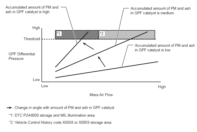
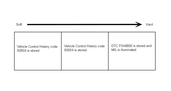
When particulate matter and ash accumulate in the GPF, it becomes difficult for the exhaust gas to flow and the GPF differential pressure increases, so the ECM limits the intake air flow to protect parts.
After the limit value of the intake air flow drops below the threshold, if a driving operation equal to or higher than the current load is performed and it is estimated that the GPF differential pressure will increase to the limit value or more, when the intake air flow reaches the limit value, excessive accumulation is detected in the GPF, a DTC is output and the MIL illuminates.
MONITOR STRATEGY
| Frequency of Operation | Once per driving cycle |
CONFIRMATION DRIVING PATTERN
Connect the GTS to the DLC3.
Turn the ignition switch to ON.
Turn the GTS on.
Clear the DTCs (even if no DTCs are stored, perform the clear DTC procedure).
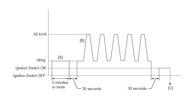
Idle the engine for 5 minutes or more [A].
Turn the ignition switch off and wait for at least 30 seconds.
Start the engine.
Repeat the pattern of accelerating the vehicle from rest to approximately 60 km/h (37 mph) [depress the accelerator pedal by a large amount at 2nd shift position] and then decelerating the vehicle 5 times [B].
- CAUTION:
-
When performing the confirmation driving pattern, obey all speed limits and traffic laws.
Turn the ignition switch off and wait for at least 30 seconds.
Turn the ignition switch to ON.
Turn the GTS on.
Enter the following menus: Powertrain / Engine / Trouble Codes [C].
Read the pending DTCs.
WIRING DIAGRAM
Refer to DTC P01052A for the manifold absolute pressure sensor circuit.
Click hereEngine / Hybrid System>1KR-FE (ENGINE CONTROL)>SFI SYSTEM>P01052A
Refer to DTC P245211 for the differential pressure sensor circuit.
Click hereEngine / Hybrid System>1KR-FE (ENGINE CONTROL)>SFI SYSTEM>P245211
CAUTION / NOTICE / HINT
- NOTICE:
-
After replacing the ECM, perform idle learning.
-
Click hereEngine / Hybrid System>1KR-FE (ENGINE CONTROL)>SFI SYSTEM>INITIALIZATION
- HINT:
- ·
Clear the Vehicle Control History after completing repairs.
Click hereEngine / Hybrid System>1KR-FE (ENGINE CONTROL)>SFI SYSTEM>VEHICLE CONTROL HISTORY
·Read Freeze Frame Data using the GTS. The ECM records vehicle and driving condition information as Freeze Frame Data the moment a DTC is stored. When troubleshooting, Freeze Frame Data can help determine if the vehicle was moving or stationary, if the engine was warmed up or not, if the air fuel ratio was lean or rich, and other data from the time the malfunction occurred.
PROCEDURE
Record the Vehicle Control History (RoB).
- Powertrain > Engine > Utility
-
Tester Display Vehicle Control History (RoB) - 50005 372 55
Read the DTCs.
- Powertrain > Engine > Trouble Codes
- 50001 372
- Result:
Result Proceed to DTC P244B00 and other DTCs are output A Vehicle Control History code X0858, X0859 or DTC P244B00 is output B
- HINT:
-
If any DTCs other than P244B00 are output, troubleshoot those DTCs first.
A
B
Pre-procedure1
None.
Procedure1
Clear the DTCs.
- Powertrain > Engine > Clear DTCs
- 50002 372
- Result:
Proceed to NEXT
Post-procedure1
Turn the ignition switch off and wait for at least 30 seconds.
NEXT
Read the values displayed on the GTS.
- Powertrain > Engine > Data List
-
Tester Display PM Deposition Ratio Bank1 - 50003 372 821
- HINT:
-
Data List item "PM Deposition Ratio Bank1" is necessary after performing particulate filter rejuvenate. Therefore, make sure check them.
- Result:
Proceed to NEXT
NEXT
Perform the PM Rejuvenate Mode.
- HINT:
-
Click hereEngine / Hybrid System>1KR-FE (ENGINE CONTROL)>SFI SYSTEM>PARTICULATE FILTER REJUVENATE PROCEDURE
- Result:
Proceed to NEXT
NEXT
Read the value displayed on the GTS.
- Powertrain > Engine > Data List
-
Tester Display PM Deposition Ratio Bank1 - 50003 372 821
- Result:
Result Proceed to The value of PM Deposition Ratio Bank1 is less than 20% A None of the above conditions are met B
- HINT:
-
After performing particulate filter rejuvenate, if the value of Data List items "PM Deposition Ratio Bank1" is less than the value during step 3 (READ VALUE USING GTS (PM DEPOSITION RATIO)), the driving condition may not be suitable for particulate filter rejuvenate. Therefore, perform particulate filter rejuvenate again.
A
B
Pre-procedure1
None.
Procedure1
Clear the DTCs.
- Powertrain > Engine > Clear DTCs
- 50002 372
- Result:
Proceed to NEXT
Post-procedure1
Turn the ignition switch off and wait for at least 30 seconds.
NEXT
Pre-procedure1
Drive the vehicle in accordance with the driving pattern described in the Confirmation Driving Pattern.
Procedure1
Read the DTCs.
- Powertrain > Engine > Trouble Codes
- 50001 372
- Result:
Result Proceed to DTCs are not output A P244B00 is output B
Post-procedure1
None.
A
B
Click hereEngine / Hybrid System>1KR-FE (EMISSION CONTROL)>DIFFERENTIAL PRESSURE SENSOR>ON-VEHICLE INSPECTION
- Result:
Proceed to OK NG
OK
NG
Read the Intake Manifold Absolute Pressure value at ignition switch ON.
- Powertrain > Engine > Data List
-
Tester Display Engine Speed Intake Manifold Absolute Pressure Coolant Temperature - 50003 372 211,385,205
- Result:
Result Proceed to The value of Intake Manifold Absolute Pressure is between 80 and 110 kPa A None of the above conditions are met B
- HINT:
-
Clear the GPF deposition values using the GTS after replacing the front exhaust pipe assembly (GPF).
A
B
Pre-procedure1
Start the engine.
Warm up the engine.
Procedure1
Read the Intake Manifold Absolute Pressure value at idling.
- Powertrain > Engine > Data List
-
Tester Display Engine Speed Intake Manifold Absolute Pressure Coolant Temperature - 50003 372 211,385,205
- Result:
Result Proceed to The value of Intake Manifold Absolute Pressure is between 29 and 37 kPa A None of the above conditions are met B
Post-procedure1
None.
A
B
Pre-procedure1
Start the engine.
Warm up the engine.
Procedure1
Read the Intake Manifold Absolute Pressure value at 2500 rpm.
- Powertrain > Engine > Data List
-
Tester Display Engine Speed Intake Manifold Absolute Pressure Coolant Temperature - 50003 372 211,385,205
- Result:
Result Proceed to The value of Intake Manifold Absolute Pressure is between 22 and 50 kPa A None of the above conditions are met B
- HINT:
-
Clear the GPF deposition values using the GTS after replacing the front exhaust pipe assembly (GPF).
Post-procedure1
None.
A
B
Pre-procedure1
Disconnect the manifold absolute pressure sensor connector.
Disconnect the ECM connector.
Procedure1
Measure the resistance according to the value(s) in the table below.
- Standard Resistance:
Tester Connection Condition Specified Condition D21-3 (VC) - D50-95 (VC2) Always Below 1 Ω D21-1 (PIM) - D50-129 (PIM) Always Below 1 Ω D21-2 (E2) - D50-127 (E21) Always Below 1 Ω D21-3 (VC) or D50-95 (VC2) - Body ground and other terminals Always 10 kΩ or higher D21-1 (PIM) or D50-129 (PIM) - Body ground and other terminals Always 10 kΩ or higher D21-2 (E2) or D50-127 (E21) - Body ground and other terminals Always 10 kΩ or higher
- Result:
Proceed to OK NG
Post-procedure1
None.
OK
NG
Pre-procedure1
Disconnect the manifold absolute pressure sensor connector.
Turn the ignition switch to ON.
Procedure1
Measure the voltage according to the value(s) in the table below.
- Standard Voltage:
Tester Connection Condition Specified Condition D21-3 (VC) - D21-2 (E2) Ignition switch ON 4.8 to 5.2 V D21-1 (PIM) - D21-2 (E2) Ignition switch ON 4.8 to 5.2 V
- Result:
Proceed to OK NG
Post-procedure1
None.
OK
NG
Pre-procedure1
Disconnect the differential pressure sensor connector.
Disconnect the ECM connector.
Procedure1
Measure the resistance according to the value(s) in the table below.
- Standard Resistance:
Tester Connection Condition Specified Condition D72-3 (VC) - A55-35 (VCPX) Always Below 1 Ω D72-2 (PEX) - A55-34 (PEX) Always Below 1 Ω D72-1 (E2) - A55-32 (EPEX) Always Below 1 Ω D72-3 (VC) or A55-35 (VCPX) - Body ground and other terminals Always 10 kΩ or higher D72-2 (PEX) or A55-34 (PEX) - Body ground and other terminals Always 10 kΩ or higher
- Result:
Proceed to OK NG
Post-procedure1
None.
OK
NG
Pre-procedure1
None.
Procedure1
Replace the differential pressure sensor.
- HINT:
-
Click hereEngine / Hybrid System>1KR-FE (EMISSION CONTROL)>DIFFERENTIAL PRESSURE SENSOR>REMOVAL
- Result:
Proceed to NEXT
Post-procedure1
Start the engine and allow it to idle until the engine coolant temperature reaches 75°C (167°F) or higher (A).
Turn the ignition switch off and wait for 30 seconds or more (B).
Repeat the above procedures (A) and (B) 3 times.
- HINT:
-
Procedures (A) and (B) must be repeated 3 times to complete the differential pressure sensor learning process.
NEXT