C551 MANUAL TRANSMISSION / TRANSAXLE BACK-UP LIGHT SWITCH REMOVAL
CAUTION / NOTICE / HINT
The necessary procedures (adjustment, calibration, initialization or registration) that must be performed after parts are removed and installed, or replaced during transmission control cable assembly removal/installation are shown below.
| Replaced Part or Performed Procedure | Necessary Procedure | Effect/Inoperative Function when Necessary Procedure not Performed | Link |
|---|---|---|---|
| Auxiliary battery terminal is disconnected/reconnected | Memorize steering angle neutral point | Parking assist monitor system | ( ) |
·
Air intake system parts ·
Exhaust system parts |
Inspection after repair | ·
Poor idle, etc. ·
Engine start function, etc. |
()
|
- HINT:
-
When the cable is disconnected / reconnected to the auxiliary battery terminal, systems temporarily stop operating. However, each system has a function that completes learning the first time the system is used.
- ·
Learning completes when vehicle is driven
Effect/Inoperative Function When Necessary Procedures are not Performed Necessary Procedures Link Lane tracing assist system Drive the vehicle straight ahead at 35 km/h (22 mph) or more for 5 second or more. ( )
Pre-collision system Stop and start system Drive the vehicle until stop and start control is permitted (approximately 5 to 60 minutes) ( )
·Learning completes when vehicle is operated normally
Effect/Inoperative Function When Necessary Procedures are not Performed Necessary Procedures Link Power door lock control system
·Back door opener
Perform door unlock operation with door control switch or electrical key transmitter sub-assembly switch. ( )
Air conditioning system After the ignition switch is turned to ON, the servo motor standard position is recognized. -
PROCEDURE

 1. PRECAUTION
- NOTICE:
-
After turning the ignition switch off, waiting time may be required before disconnecting the cable from the negative (-) battery terminal.
-
Click hereGeneral>SETUP>WHEN DISCONNECTING OR RECONNECTING BATTERY TERMINAL>BEFORE DISCONNECTING BATTERY
2.DISCONNECT CABLE FROM NEGATIVE BATTERY TERMINAL
51451A
3.REMOVE CENTER ENGINE UNDER COVER
51442C
4.REMOVE ENGINE UNDER COVER LH
51441C
5.REMOVE ENGINE UNDER COVER RH
6.REMOVE WINDSHIELD WIPER MOTOR AND LINK ASSEMBLY
55815E
7.REMOVE FRONT NO. 1 VENTILATOR SEAL (for LHD)
55815E
8.REMOVE FRONT NO. 1 VENTILATOR SEAL (for RHD)
55734A
9.REMOVE WATER GUARD PLATE RH (for LHD)
55735A
10.REMOVE WATER GUARD PLATE LH (for RHD)
55701J
11.REMOVE OUTER COWL TOP PANEL SUB-ASSEMBLY (for LHD)
55701J
12.REMOVE OUTER COWL TOP PANEL SUB-ASSEMBLY (for RHD)
13.REMOVE AIR CLEANER CAP WITH AIR CLEANER HOSE
17801
14.REMOVE AIR CLEANER FILTER ELEMENT SUB-ASSEMBLY
17701
15.REMOVE AIR CLEANER CASE SUB-ASSEMBLY
89661
16.REMOVE ECM
74404A
17.REMOVE BATTERY CLAMP SUB-ASSEMBLY
82121
18.DISCONNECT ENGINE WIRE
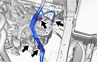
w/ Stop and Start System
Disconnect the neutral position switch connector.
Remove the bolt and disconnect the engine wire.
Remove the 2 bolts and separate the engine wire protector.
19.INSTALL ENGINE HANGERS
20.INSTALL ENGINE SUPPORT BRIDGE
12372A
21.REMOVE ENGINE MOUNTING INSULATOR LH
12325A
22.REMOVE ENGINE MOUNTING BRACKET LH
84210
23.REMOVE BACK-UP LIGHT SWITCH ASSEMBLY
Disconnect the back-up light switch connector.
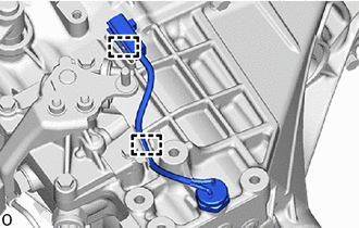
Disengage the 2 wire harness clamps.
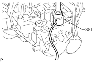
Using SST, remove the back-up light switch assembly and gasket from the manual transaxle assembly.
- SST
- 09817-16011