1KR-FE ENGINE MECHANICAL ENGINE ASSEMBLY REMOVAL
CAUTION / NOTICE / HINT
- NOTICE:
-
As the engine assembly with transaxle is extremely heavy, the engine lifter may suddenly drop if the instructions listed in the repair manual are not followed. Therefore, always follow the instructions listed in the repair manual when performing this procedure.
- HINT:
-
When the cable is disconnected/reconnected to the auxiliary battery terminal, systems temporarily stop operating. However, each system has a function that completes learning the first time the system is used.
- ·
Learning completes when vehicle is driven
Effect/Inoperative Function When Necessary Procedures are not Performed Necessary Procedures Link Lane tracing assist system Drive the vehicle straight ahead at 35 km/h (22 mph) or more for 5 second or more. (  )
Pre-collision system Stop and start system Drive the vehicle until stop and start control is permitted (approximately 5 to 60 minutes) ( )
·Learning completes when vehicle is operated normally
Effect/Inoperative Function When Necessary Procedures are not Performed Necessary Procedures Link Power door lock control system
·Back door opener
Perform door unlock operation with door control switch or electrical key transmitter sub-assembly switch. ( )
Air conditioning system After the ignition switch is turned to ON, the servo motor standard position is recognized. -
PROCEDURE

 1. PRECAUTION
- NOTICE:
-
After turning the engine switch off, waiting time may be required before disconnecting the cable from the negative (-) auxiliary battery terminal. Therefore, make sure to read the disconnecting the cable from the negative (-) auxiliary battery terminal notices before proceeding with work.
-
Click hereGeneral>INTRODUCTION>REPAIR INSTRUCTION>PRECAUTION
2.RECOVER REFRIGERANT FROM REFRIGERATION SYSTEM
3. DISCHARGE FUEL SYSTEM PRESSURE
4. ALIGN FRONT WHEELS FACING STRAIGHT AHEAD
28800
5.REMOVE BATTERY
6.REMOVE FRONT WHEELS
51451A
7.REMOVE CENTER ENGINE UNDER COVER
51442C
8.REMOVE ENGINE UNDER COVER LH
51441C
9.REMOVE ENGINE UNDER COVER RH
10.DRAIN ENGINE OIL
11.DRAIN ENGINE COOLANT
12.DRAIN MANUAL TRANSAXLE OIL
13.REMOVE WINDSHIELD WIPER MOTOR AND LINK
55815E
14.REMOVE NO. 1 FRONT VENTILATOR SEAL (for LHD)
55815E
15.REMOVE NO. 1 FRONT VENTILATOR SEAL (for RHD)
55734A
16.REMOVE WATER GUARD PLATE RH (for LHD)
55735A
17.REMOVE WATER GUARD PLATE LH (for RHD)
55701J
18.REMOVE OUTER COWL TOP PANEL SUB-ASSEMBLY (for LHD)
55701J
19.REMOVE OUTER COWL TOP PANEL SUB-ASSEMBLY (for RHD)
17735
20.REMOVE AIR CLEANER ASSEMBLY WITH DUCT
17801
21.REMOVE AIR CLEANER FILTER ELEMENT SUB-ASSEMBLY
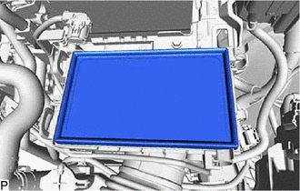
Remove the air cleaner filter element sub-assembly from the air cleaner case sub-assembly.
17701
22.REMOVE AIR CLEANER CASE SUB-ASSEMBLY
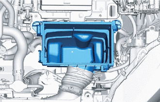
Remove the air cleaner case sub-assembly from the vehicle.
23.REMOVE ECM
74404A
24.REMOVE BATTERY CLAMP SUB-ASSEMBLY
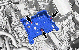
Remove the 3 bolts and battery clamp sub-assembly from the vehicle.
82662A
25.REMOVE NO. 1 RELAY BLOCK COVER
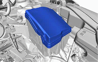
Remove the No. 1 relay block cover from the engine room relay block.
82121
26.DISCONNECT ENGINE WIRE
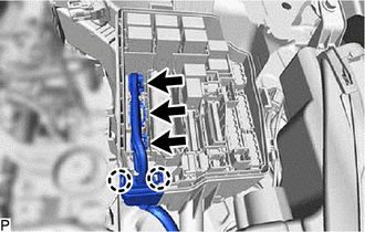
Disconnect the 3 connectors from the engine room relay block.
Disengage the 2 claws to separate the engine wire from the engine room relay block.
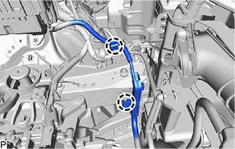
Disengage the 2 claws to separate the engine wire from the vehicle.
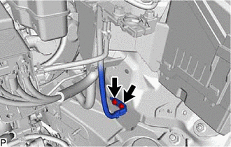
Remove the 2 bolts to separate the engine wire from the vehicle.
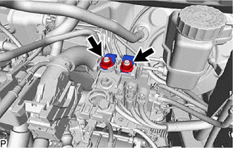
Remove the 2 nuts to separate the engine wire from the positive (+) battery terminal.
27020
27.REMOVE GENERATOR ASSEMBLY
for 80A Type:
Click herePower Source / Network>1KR-FE (BATTERY / CHARGING)>GENERATOR (for 80A Type)>REMOVAL
for 100A Type:
Click herePower Source / Network>1KR-FE (BATTERY / CHARGING)>GENERATOR (for 100A Type)>REMOVAL
88310
28.SEPARATE COMPRESSOR ASSEMBLY WITH PULLEY
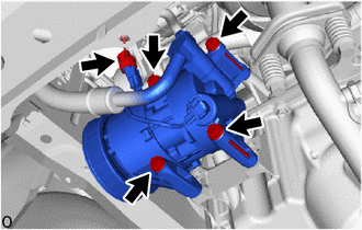
Disconnect the compressor assembly with pulley connector.
Remove the 4 bolts to separate the compressor assembly with pulley from the cylinder block sub-assembly and oil pan sub-assembly.
- HINT:
-
It is not necessary to completely remove the compressor assembly with pulley. With the No. 1 cooler refrigerant discharge hose suction hose sub-assembly connected to the compressor, hang the compressor on the vehicle body with a rope.
23841B
29.REMOVE EFI FUEL PIPE CLAMP
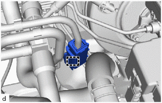
Disengage the claw and remove the No. 1 fuel pipe clamp.
23901
30.DISCONNECT FUEL TUBE SUB-ASSEMBLY
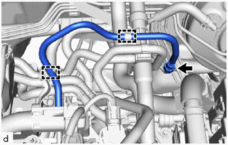
Disengage the 2 claws and disconnect the fuel tube sub-aseembly.
Click hereEngine / Hybrid System>1KR-FE (FUEL)>FUEL SYSTEM>PRECAUTION
23826
31.SEPARATE NO. 1 FUEL VAPOR FEED HOSE
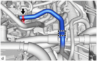
Disengage the clamp to disconnect the No. 1 fuel vapor feed hose from the hose clamp.
Slide the hose clip and disconnect the No. 1 fuel vapor feed hose from the duty vacuum switching valve.
87246
32.DISCONNECT OUTLET HEATER WATER HOSE
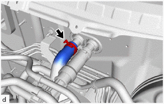
Slide the hose clip and disconnect the outlet heater water hose from the heater unit.
87245
33.DISCONNECT INLET HEATER WATER HOSE
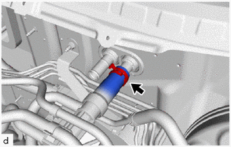
Slide the hose clip and disconnect the inlet heater water hose from the heater unit.
34.DISCONNECT VACUUM HOSE ASSEMBLY
16571C
35.SEPARATE NO. 1 RADIATOR HOSE
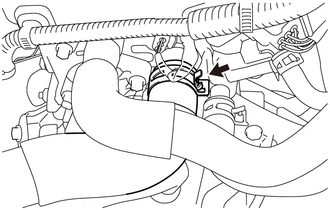
Slide the hose clip and disconnect the No. 1 radiator hose from the cylinder head sub-assembly.
16572D
36.SEPARATE NO. 2 RADIATOR HOSE
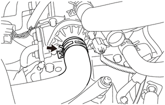
Slide the hose clip and disconnect the No. 2 radiator hose from the water inlet.
57543C
37.REMOVE FRONT FLOOR CENTER BRACE
17410
38.REMOVE FRONT EXHAUST PIPE ASSEMBLY
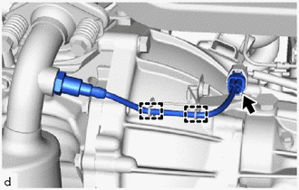
Disconnect the No. 2 heated oxygen sensor connector.
Disengage the 2 clamps to disconnect the No. 2 heated oxygen sensor connector wire from the wire harness clamp bracket.
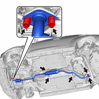
Remove the 2 bolts, 2 compression spring to separate the front exhaust pipe assembly from the tail exhaust pipe assembly.
Remove the 2 bolts, 2 compression spring to separate the front exhaust pipe assembly from the exhaust manifold.
Disconnect the 3 exhaust pipe supports to remove the front exhaust pipe assembly from the vehicle.
Remove the exhaust pipe gasket from the exhaust manifold.
Remove the No. 2 exhaust pipe gasket from the front exhaust pipe assembly.
31461
39.REMOVE RELEASE CYLINDER HEAT INSULATOR
31470
40.SEPARATE CLUTCH RELEASE CYLINDER ASSEMBLY
33820B
41.DISCONNECT TRANSMISSION CONTROL CABLE ASSEMBLY
43498A
42.REMOVE DRIVE SHAFT HEAT INSULATOR SUB-ASSEMBLY
43.REMOVE FRONT DRIVE SHAFT ASSEMBLY
45259A
44.REMOVE COLUMN HOLE COVER SILENCER SHEET (for LHD)
45259A
45.REMOVE COLUMN HOLE COVER SILENCER SHEET (for RHD)
45260
46.DISCONNECT NO. 2 STEERING INTERMEDIATE SHAFT ASSEMBLY
47.REMOVE ENGINE ASSEMBLY WITH TRANSAXLE
Set the engine assembly with transaxle on an engine lifter.
- NOTICE:
- ·
Using height adjustment attachments and plate lift attachments, keep the engine assembly with transaxle and front suspension crossmember sub-assembly level.
·Do not perform any procedures while the engine assembly is suspended because doing so may cause the engine assembly to drop, resulting in injury. However, the engine assembly needs to be suspended when it is installed to or removed from an engine stand.
·To prevent the engine assembly from unexpectedly moving, securely support the engine assembly until it is secured to an engine stand.
·To prevent the oil pan sub-assembly from deforming, do not place any attachments under the oil pan sub-assembly of the engine assembly with transaxle.
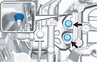
Remove the 2 bolts and nut and separate the engine mounting insulator sub-assembly RH from the engine mounting bracket RH.
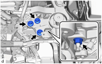
Remove the 3 bolts and nut and separate the engine mounting insulator LH from the hybrid vehicle transaxle assembly.
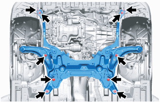
Remove the 10 bolts to separate the front suspension crossmember sub-assembly from the vehicle.
Operate the engine lifter and remove the engine assembly with transaxle from the vehicle.
- NOTICE:
- ·
Make sure that the engine assembly with transaxle is clear of all wiring and hoses.
·While lowering the engine assembly with transaxle from the vehicle, do not allow it to contact the vehicle.
48.INSTALL ENGINE HANGER
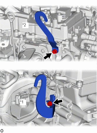
| *1 | No. 1 Engine Hanger |
| *2 | No. 2 Engine Hanger |
Install the No. 1 engine hanger and No. 2 engine hanger to the cylinder head sub-assembly with the 2 bolts.
- Torque:
- 28 N*m (286 kgf*cm, 21 ft.*lbf)
- HINT:
Part Name Part No. No. 1 Engine Hanger 12281-40032 No. 2 Engine Hanger 12282-40010 Bolt 91551-80820 or 90105-W0112
82121
49.REMOVE ENGINE WIRE
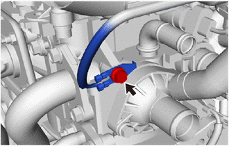
Remove the bolt to disconnect the engine wire from the cylinder head sub-assembly.
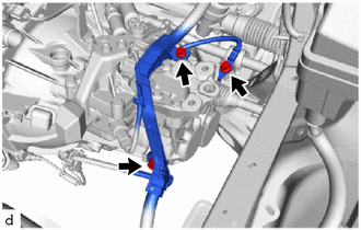
Remove the 3 bolts to disconnect the engine wire from the transaxle.
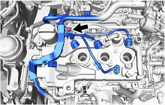
Remove the bolt to disconnect the engine wire from the cylinder head cover sub-assembly.
Disconnect all the wire harnesses and connectors. Make sure that no wire harnesses are connected to the engine assembly.
11363A
50.REMOVE FLYWHEEL HOUSING SIDE COVER
28100
51.REMOVE STARTER ASSEMBLY (w/ Stop And Start System)
28100
52.REMOVE STARTER ASSEMBLY (w/o Stop And Start System)
30300
53.REMOVE MANUAL TRANSAXLE ASSEMBLY
31210
54.REMOVE CLUTCH COVER ASSEMBLY
31250
55.REMOVE CLUTCH DISC ASSEMBLY
13405
56.REMOVE FLYWHEEL SUB-ASSEMBLY
57.INSTALL ENGINE STAND
Install the engine assembly to an engine stand.
- NOTICE:
- ·
Adjust the angle of the sling device carefully to prevent the engine assembly or engine hangers from deforming or becoming damaged.
·Servicing an engine assembly while it is hanging is dangerous. This can be done only when installing/removing the engine assembly to/from an engine stand.
12305
58.REMOVE ENGINE MOUNTING INSULATOR SUB-ASSEMBLY RH
- HINT:
-
Only perform this procedure when replacement of the engine mounting insulator sub-assembly RH is necessary.
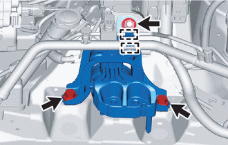
Remove the clamp and disconnect the air conditioner tube.
Remove the 2 bolts, nut and engine mounting insulator sub-assembly RH from the vehicle.
12372A
59.REMOVE ENGINE MOUNTING INSULATOR LH
- HINT:
-
Only perform this procedure when replacement of the engine mounting insulator LH is necessary.
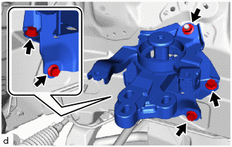
Remove the 4 bolts, nut and engine mounting insulator LH from the vehicle.
60.REMOVE ENGINE HANGER
Remove the 2 bolts, No. 1 engine hanger and No. 2 engine hanger from the cylinder head sub-assembly.