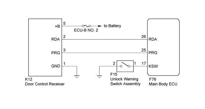
WIRELESS DOOR LOCK CONTROL SYSTEM > Only Wireless Control Function is Inoperative |
| 1.CHECK POWER DOOR LOCK OPERATION |
When the door control switch on the power window regulator master switch assembly is operated, check that the locked doors unlock (Click here).
|
| ||||
| OK | |
 |
| 2.INSPECT UNLOCK WARNING SWITCH ASSEMBLY |
Inspect the unlock warning switch assembly (Click here).
|
| ||||
| OK | |
|
| 3.CHECK HARNESS AND CONNECTOR (MAIN BODY ECU - UNLOCK WARNING SWITCH ASSEMBLY) |
Disconnect the F76 main body ECU connector.
Disconnect the F15 unlock warning switch assembly connector.
Measure the resistance according to the value(s) in the table below.
| Tester Connection | Condition | Specified Condition |
| F76-17 (KSW) - F15-1 | Always | Below 1 Ω |
| F76-17 (KSW) - Body ground | Always | 10 kΩ or higher |
|
| ||||
| OK | |
|
| 4.SWITCH TO SELF DIAGNOSTIC MODE |
Switch to self-diagnostic mode.
Connect the intelligent tester to the DLC3.
Turn the ignition switch to ON.
Turn the intelligent tester on.
Enter following menus: Body / Main Body / Utility / Wireless Door Lock Diagnosis Mode
Proceed to the next step in accordance with the prompts on the intelligent tester screen.
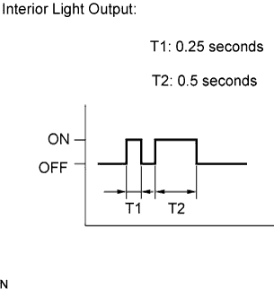 |
Check that the system has switched to self-diagnostic mode by checking the map light assembly flash pattern.
| NEXT | |
|
| 5.CHECK BY SELF DIAGNOSTIC MODE |
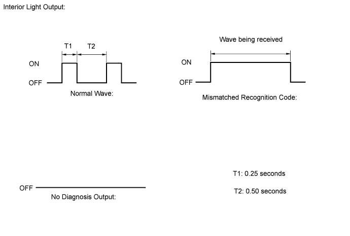
Inspect the diagnosis outputs when the door control transmitter switch is held down. The diagnosis outputs can be checked by the flash patterns of the map light assembly.
| Result | Proceed to |
| Normal waves (light flash patterns) for lock and unlock switches are output | A |
| Unmatching recognition code is output | B |
| No diagnosis outputs | C |
|
| ||||
|
| ||||
| A | ||
 | ||
| ||
| 6.REGISTER RECOGNITION CODE |
Check that the system can be switched to rewrite mode or add mode, and that a recognition code can be registered.
|
| ||||
| OK | ||
| ||
| ||
| 7.CHECK RESPONSE OF DOOR CONTROL RECEIVER (RESPONSE) |
Prepare the door control transmitter from another vehicle.
Press and hold down the door control transmitter switch.
Check that an unmatching recognition code is output.
|
| ||||
| OK | |
|
| 8.INSPECT TRANSMITTER BATTERY (VOLTAGE) |
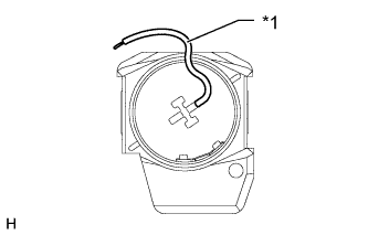 |
Remove the battery from the door control transmitter module that does not operate. Attach a lead wire (0.6 mm (0.0236 in.)) or less in diameter including wire sheath) with tape or equivalent to the negative terminal (Click here).
| *1 | Lead Wire |
Carefully pull the lead wire out from the position shown in the illustration and install the previously removed transmitter battery.
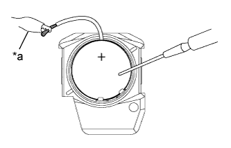 |
Measure the voltage according to the value(s) in the table below.
| Tester Connection | Condition | Specified Condition |
| Battery positive (+) - Battery negative (-) | Ignition switch off, all doors closed and lock or unlock switch pushed | 2.5 to 3.2 V |
| *a | GND |
|
| ||||
| OK | ||
| ||
| ||
| 9.REPLACE TRANSMITTER BATTERY |
Replace the transmitter battery (Click here).
| NEXT | |
|
| 10.CHECK BY SELF DIAGNOSTIC MODE |
Inspect the diagnosis outputs when the door control transmitter switch is held down. The diagnosis outputs can be checked by the flash patterns of the No. 1 room light assembly.
| Result | Proceed to |
| Normal waves (light flash patterns) for LOCK and UNLOCK switches are output | A |
| Unmatching recognition code is output | B |
| No diagnosis outputs |
|
| ||||
| A | ||
| ||
| ||
| 11.CHECK WAVE ENVIRONMENT |
Bring the transmitter near the door control receiver, and perform a wireless operation check.
|
| ||||
| OK | |
|
| 12.INSPECT DOOR CONTROL RECEIVER (POWER SOURCE, GROUND) |
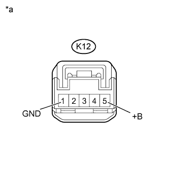 |
Disconnect the K12 door control receiver connector.
Measure the resistance and voltage according to the value(s) in the table below.
| Tester Connection | Condition | Specified Condition |
| K12-1 (GND) - Body ground | Always | Below 1 Ω |
| Tester Connection | Condition | Specified Condition |
| K12-5 (+B) - Body ground | Always | 11 to 14 V |
| *a | Front view of wire harness connector (to Door Control Receiver) |
Reconnect the K12 door control receiver connector.
|
| ||||
| OK | |
|
| 13.INSPECT DOOR CONTROL RECEIVER (OUTPUT) |
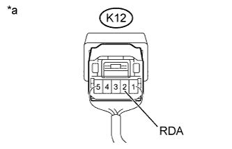 |
Measure the voltage according to the value(s) in the table below.
| Tester Connection | Switch Condition | Specified Condition |
| K12-2 (RDA) - Body ground | Ignition switch off, all doors closed and door control transmitter switch off | 11 to 14 V |
| Ignition switch off, all doors closed and door control transmitter switch on | pulse generation |
| *a | Component with harness connected (Door Control Receiver) |
| Result | Proceed to |
| OK | A |
| NG (for 5 Door) | B |
| NG (for 3 Door) | C |
|
| ||||
|
| ||||
| A | |
|
| 14.CHECK HARNESS AND CONNECTOR (MAIN BODY ECU - DOOR CONTROL RECEIVER) |
Disconnect the F76 main body ECU connector.
Disconnect the K12 door control receiver connector.
Measure the resistance according to the value(s) in the table below.
| Tester Connection | Condition | Specified Condition |
| F76-26 (RDA) - K12-2 (RDA) | Always | Below 1 Ω |
| F76-26 (RDA) or K12-2 (RDA) - Body ground | Always | 10 kΩ or higher |
| F76-25 (PRG) - K12-3 (PRG) | Always | Below 1 Ω |
| F76-25 (PRG) or K12-3 (PRG) - Body ground | Always | 10 kΩ or higher |
Reconnect the main body ECU connector and door control receiver connector.
|
| ||||
| OK | |
|
| 15.REPLACE DOOR CONTROL RECEIVER |
Temporarily replace the door control receiver with a new or normally functioning one.
| NEXT | |
|
| 16.REGISTER RECOGNITION CODE |
Perform the Registration procedures (Click here).
| NEXT | |
|
| 17.CHECK DOOR CONTROL RECEIVER (OPERATION) |
Check that the doors can be locked and unlocked by using the transmitter LOCK and UNLOCK switches.
|
| ||||
| OK | ||
| ||
| ||

