INSTRUMENT PANEL ASSEMBLY
REMOVAL
NOTE: Before starting this procedure, be certain to turn the steering wheel until the front wheels are in the straight-ahead position.
1. Before proceeding with the following repair procedure, review all warnings and cautions. (Refer to 23 - BODY/INSTRUMENT PANEL - WARNING)
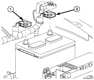
2. Disconnect and isolate the battery negative cable.
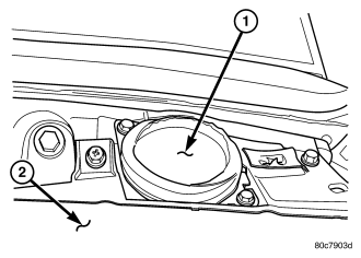
3. Remove the instrument panel speakers. (Refer to 8 - ELECTRICAL/AUDIO/SPEAKER - REMOVAL)
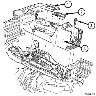
4. Remove the floor console. (Refer to 23 - BODY/INTERIOR/FLOOR CONSOLE - REMOVAL)
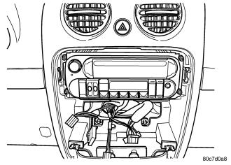
5. Remove the radio. (Refer to 8 - ELECTRICAL/AUDIO/RADIO - REMOVAL)
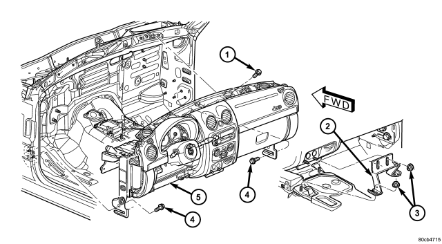
6. Remove the four nuts (3) and remove the center support bracket (2).
7. Remove the ground strap bolt and disconnect the restraint module electrical connector.
8. Position front wheels straight ahead.
9. Remove knee blocker cover and knee blocker. (Refer to 23 - BODY/INSTRUMENT PANEL/KNEE BLOCKER - REMOVAL)
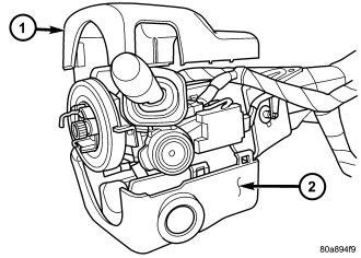
10. Remove screws from the lower column shroud and remove both the upper (1) and lower (2) shrouds.
11. Turn ignition key to the on position.
12. Disconnect the automatic transmission shifter interlock cable from the column, if equipped.
CAUTION: Do not turn the clockspring more than 90° or damage to the clockspring may occur.
13. Using a grease pencil or equivalent, mark the position of the steering wheel.
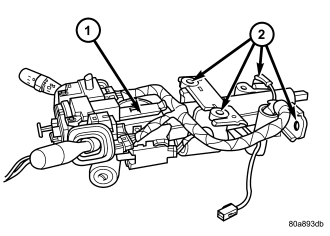
14. Remove the steering coupler bolt and column mounting nuts and bolts then lower column off the mounting studs.
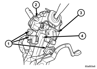
15. Disconnect and remove the wiring harness from the column.
16. Slide the shifter interlock cable from the tie straps.
17. Remove the steering column.
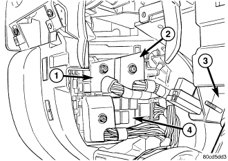
CAUTION: Do not remove the brake lamp switch. This is a one time component and is not intended for reinstallation. If the brake lamp switch is removed it must be discarded and replaced with a new switch.
18. Disconnect the brake lamp switch electrical connector.
19. Remove the drivers side cowl trim cover. (Refer to 23 - BODY/INTERIOR/COWL TRIM COVER - REMOVAL)
20. Disconnect the wire harness connector behind the drivers side cowl trim cover.
21. Disconnect the green and light blue wire harness bulk connectors at the junction block.
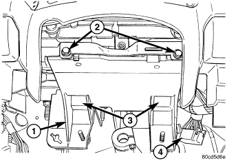
22. Disconnect the electrical connector at the inner side of the pedal support bracket.
23. Remove the two bolts at the front of the pedal support bracket.
24. Remove the two bolts from the bottom side of the pedal support bracket.
25. Remove the two roll down bracket bolts at the drivers cowl side panel.
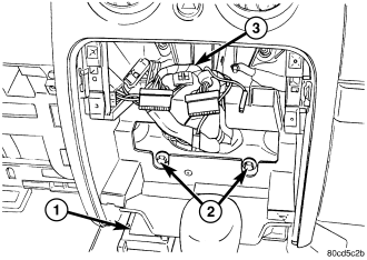
26. Remove the glove box. (Refer to 23 - BODY/INSTRUMENT PANEL/GLOVE BOX - REMOVAL)
27. Remove the two HVAC mounting bolts behind the center trim.
28. Remove the passenger side trim bezel. (Refer to 23 - BODY/INSTRUMENT PANEL/INSTRUMENT PANEL PASSENGER SIDE BEZEL - REMOVAL)
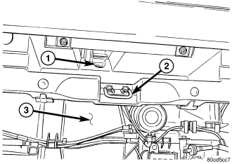
29. Remove the HVAC mounting bolt above the glove box striker.
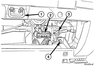
30. Remove the HVAC bolt at the lower outside corner of the glove box opening.
31. Remove the passenger side cowl trim cover. (Refer to 23 - BODY/INTERIOR/COWL TRIM COVER - REMOVAL)
32. Disconnect the blower resistor electrical connector.
33. Remove the two roll down bracket bolts at the passenger cowl side panel.
34. Disconnect the vacuum check valve and the vacuum reservoir.
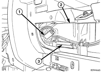
35. Disconnect the blower motor electrical connector.
36. Disconnect the blend door connector.
37. Remove the four bolts at the top of the instrument panel connecting to the cowl front panel.
38. Roll the instrument panel rearward and remove the wire harness from routing channel in the rear.
39. Disconnect the push pin fastener and position aside the radio wire harness. Note the location of the harness for installation.
40. Remove the instrument panel.
INSTALLATION
1. Before proceeding with the following repair procedure, review all warnings and cautions. (Refer to 23 - BODY/INSTRUMENT PANEL - WARNING)
2. Position the instrument panel into the vehicle.
3. Position the wire harness into the rear routing channel and roll the instrument panel back against the cowl.
4. Position the radio wire harness and seat the push pin fastener.
NOTE: Position the speaker wires through the speaker openings.
5. Install the four bolts at the top of the instrument panel connecting to the cowl front panel and tighten to 28 N·m (21 ft. lbs.).
6. Connect the blend door electrical connector.
7. Connect the blower motor electrical connector.
8. Connect the vacuum check valve and the vacuum reservoir.
9. Connect the blower resister electrical connector.
NOTE: Do not push or pull bracket. Tighten at the rest position.
10. Install the two roll down bracket bolts at the passenger cowl side panel and tighten to 54 N·m (40 ft. lbs.).
11. Install the HVAC mounting bolt at the lower outside corner of the glove box opening and tighten to 6 N·m (55 in. lbs.).
12. Install the HVAC mounting bolt above the glove box striker.
13. Install the passenger side trim bezel. (Refer to 23 - BODY/INSTRUMENT PANEL/INSTRUMENT PANEL PASSENGER SIDE BEZEL - INSTALLATION)
14. Install the passenger side cowl trim cover. (Refer to 23 - BODY/INTERIOR/COWL TRIM COVER - INSTALLATION)
15. Install the two HVAC mounting bolts behind the center trim.
16. Install the glove box. (Refer to 23 - BODY/INSTRUMENT PANEL/GLOVE BOX - INSTALLATION)
NOTE: Do not push or pull bracket. Tighten at the rest position.
17. Install the two roll down bracket bolts at the driver's cowl side panel and tighten to 54 N·m (40 ft. lbs.).
18. Install the two bolts at the bottom side of the pedal support bracket (3).
19. Install the two bolts (2) at the front of the pedal support bracket.
20. Connect the electrical connector at the inner side of the pedal support bracket.
21. Connect the wiring harness electrical connectors at the junction block.
22. Connect the wire harness electrical connector behind the driver's side cowl trim cover.
23. Install the driver's side cowl trim cover. (Refer to 23 - BODY/INTERIOR/COWL TRIM COVER - INSTALLATION)
CAUTION: Do not remove the brake lamp switch. This is a one time component and is not intended for reinstallation. If the brake lamp switch is removed it must be discarded and replaced with a new switch.
24. Connect the brake lamp switch electrical connector.
25. Install the steering column into the vehicle.
26. Slide the shifter interlock cable into the tie straps.
27. Install and connect the wire harness for the column.
28. Install the two mounting nuts and the two mounting bolts all finger tight.
CAUTION: Lower nuts must be installed and tightened first then the upper nuts in order to prevent damage to the capsules.
29. Tighten the lower mounting nuts to 17 N·m (13 ft. lbs.).
30. Tighten the upper mounting nuts to 17 N·m (13 ft. lbs.).
31. Install the steering column coupler bolt and tighten to 49 N·m (36 ft. lbs.).
32. Install the upper and lower shrouds and install the screws.
33. Install the knee blocker cover and knee blocker. (Refer to 23 - BODY/INSTRUMENT PANEL/KNEE BLOCKER - INSTALLATION)
34. Install the ground strap and bolt and connect the restraint module electrical connector.
35. Install the center support bracket (2) and hold it tight against the instrument panel.
36. Tighten the lower nuts to 23 N·m (17 ft. lbs.).
37. Tighten the upper bracket nuts to 23 N·m (17 ft. lbs.).
38. Install the radio. (Refer to 8 - ELECTRICAL/AUDIO/RADIO - INSTALLATION)
39. Install the floor console. (Refer to 23 - BODY/INTERIOR/FLOOR CONSOLE - INSTALLATION)
40. Install the speakers. (Refer to 8 - ELECTRICAL/AUDIO/SPEAKER - INSTALLATION)
41. Reconnect the battery ground cable.