A/T Assembly Dismounting and Remounting (M16A Model)
Precautions: Precautions for Diagnosing Trouble · Precautions for Disassembly and Reassembly · Precautions for Transmission / Transaxle · General safety (00)
 CAUTION:
If the transaxle assembly is tilted with the torque converter end down, the torque converter can fall off the A/T assembly, which could cause personal injury.
Keep the A/T assembly horizontal or tilted with the torque converter end up throughout the operation.
NOTE:
When A/T assembly is replaced, perform TCM Learning Value Clearance, Neutral Position Calibration and TCM Learning Value Initialization.
Dismounting
1)Remove air cleaner assembly. 
2)Remove battery and battery bracket.
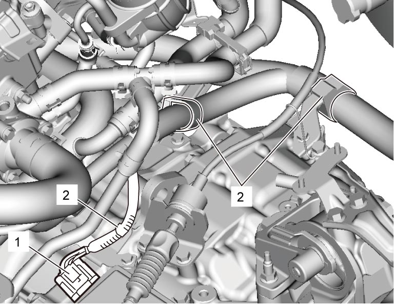
3)Disconnect TCM connector (1) and each clamp (2).

4)Disconnect select cable.
5)Hoist vehicle.
6)Remove engine undercover.
7)Drain coolant.
8)Drain ATF, if necessary.
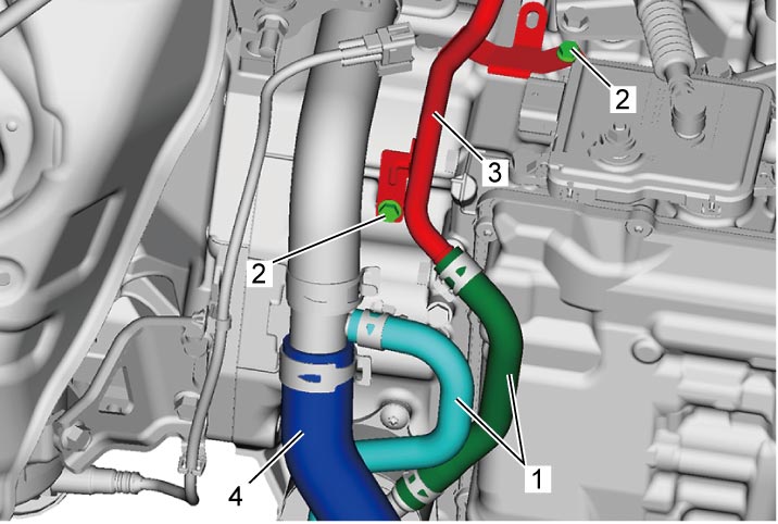
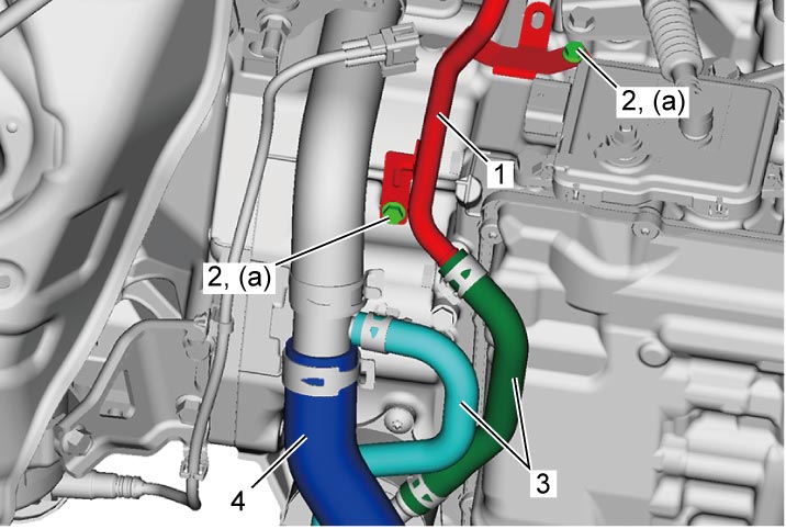
9)Disconnect ATF cooler hoses (1).
10)Remove ATF cooler pipe bolts (2) and remove ATF cooler pipe (3).
11)Disconnect radiator outlet hose (4) from radiator.
12)Remove left front fender lining.
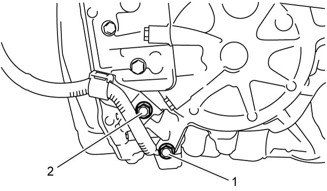
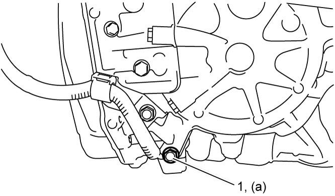
13)Remove battery ground cable bolt (1) and bracket bolt (2).
14)Remove front drive shaft assembly.
15)Remove exhaust No.1 pipe.
16)For 4WD model, remove propeller shaft.
17)For 4WD model, remove transfer assembly.
18)Remove starting motor.
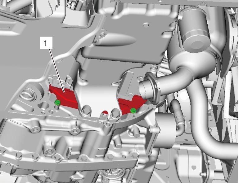
19)Remove clutch housing lower plate (1).
20)Remove torque converter bolts as follows.
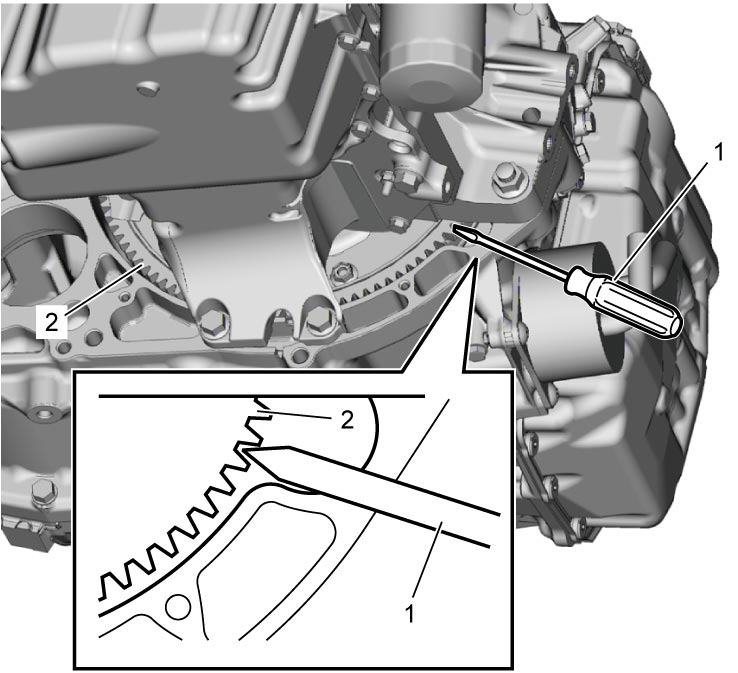
a)Insert flat-bladed screwdriver or the like (1) to torque converter housing.
b)Lock drive plate (2) by engaging flat-bladed screwdriver or the like with gear of drive plate as shown in figure.
c)Remove torque converter locating bolt (1) or torque converter bolt (2).
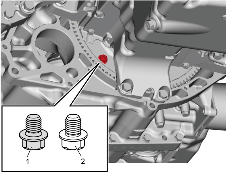
d)Turn crankshaft 60° by turning crankshaft pulley bolt using wrench.
e)Repeat Step c) – d) 5 times.
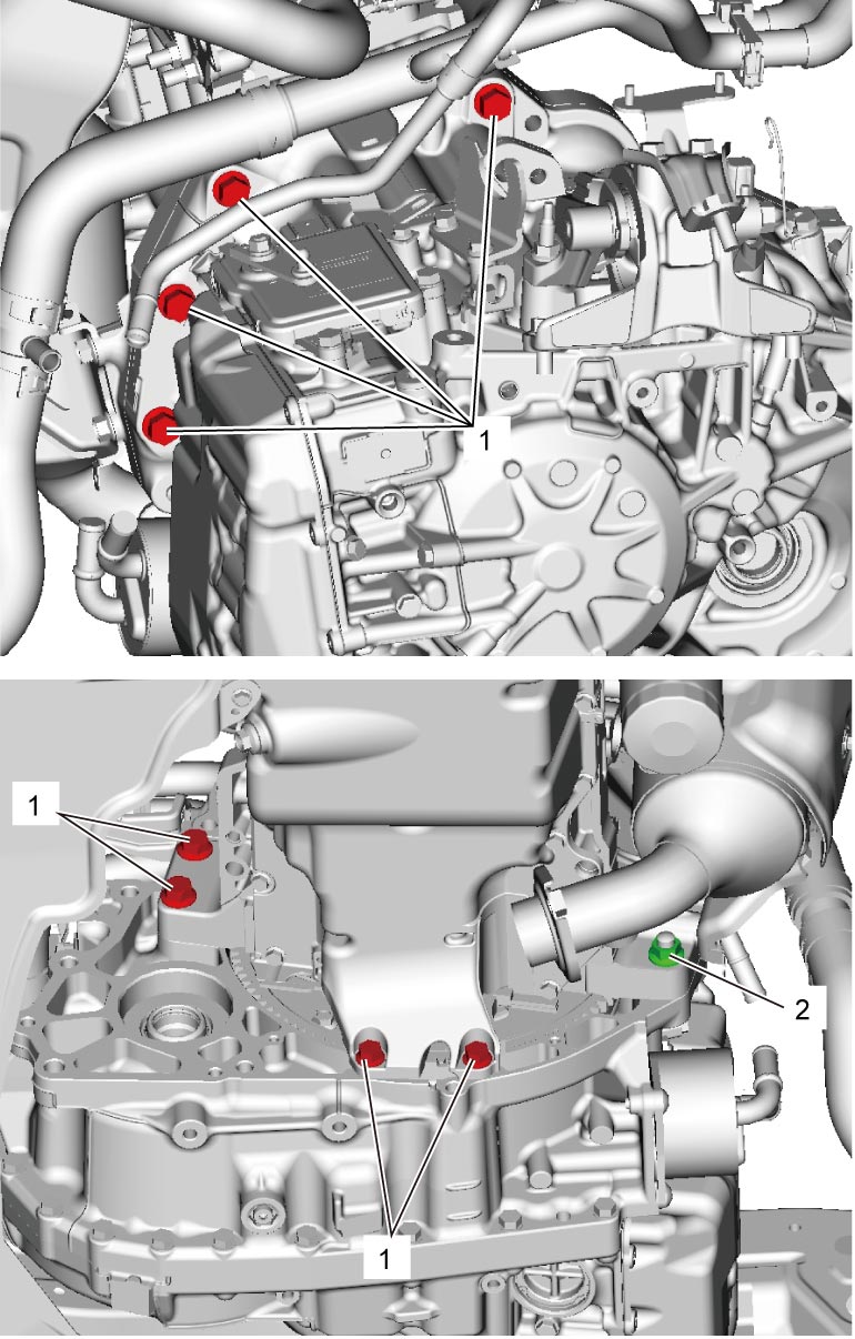
21)Loosen bolts (1) and nut (2) fastening engine and A/T assembly.
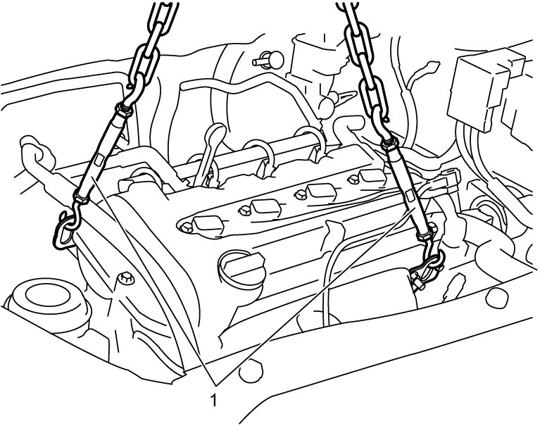
22)Support engine assembly using chain hoist (1) or engine crane.
23)Remove the following parts.
•Engine rear torque rod
•Engine rear torque rod bracket
•Engine left mounting No.1 bracket
•Engine left mounting No.2 bracket
•Engine rear torque rod bracket
•Engine left mounting No.1 bracket
•Engine left mounting No.2 bracket
24)Support A/T assembly with transmission jack (1).
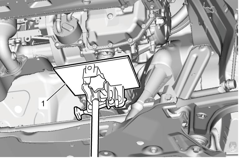
25)Remove bolts (1) and nut (2) fastening engine and A/T assembly, and then dismount A/T assembly from engine.
NOTE:
When dismounting A/T assembly from engine, move it in parallel with crankshaft and use care so as not to apply excessive force to drive plate and torque converter.
26)For 4WD model, remove transmission and transfer stiffener, if necessary.
Remounting
1)Check that torque converter is installed correctly to transaxle.
2)Remount A/T assembly to engine.
3)Tighten bolts and nuts fastening engine and A/T assembly to specified torque.
4)Install the following parts.
•Engine rear torque rod
•Engine rear torque rod bracket
•Engine left mounting No.1 bracket
•Engine left mounting No.2 bracket
•Engine rear torque rod bracket
•Engine left mounting No.1 bracket
•Engine left mounting No.2 bracket
5)Tighten torque converter locating bolt and torque converter bolts as follows.
NOTE:
Torque converter locating bolt is used for accurate positioning.
Tighten torque converter locating bolt first so that bolt holes for torque converter and drive plate are positioned properly, and that torque converter bolts are tightened securely.
One torque converter locating bolt and five torque converter bolts are required to secure torque converter and drive plate.
a)Insert flat-bladed screwdriver or the like (1) into torque converter housing.
b)Lock drive plate (2) by engaging flat-bladed screwdriver or the like with gear of drive plate as shown in figure.
c)Tighten torque converter locating bolt (1) to specified torque.
d)Turn crankshaft 60° by turning crankshaft pulley bolt using wrench and tighten torque converter bolt (2) to specified torque.
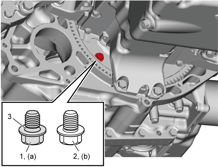
| 3. | Taper |
e)Repeat Step d) 4 times.
6)Install clutch housing lower plate (1) and tighten clutch housing lower plate bolts to specified torque.
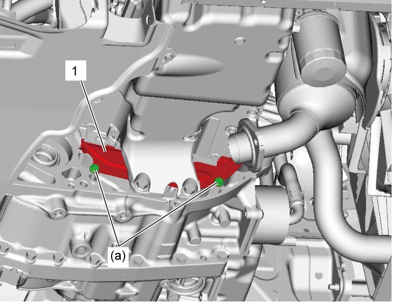
7)Install starting motor.
8)For 4WD model, install transfer assembly as follows.
a)Tighten transmission and transfer stiffener bolt (1) temporarily, if removed.
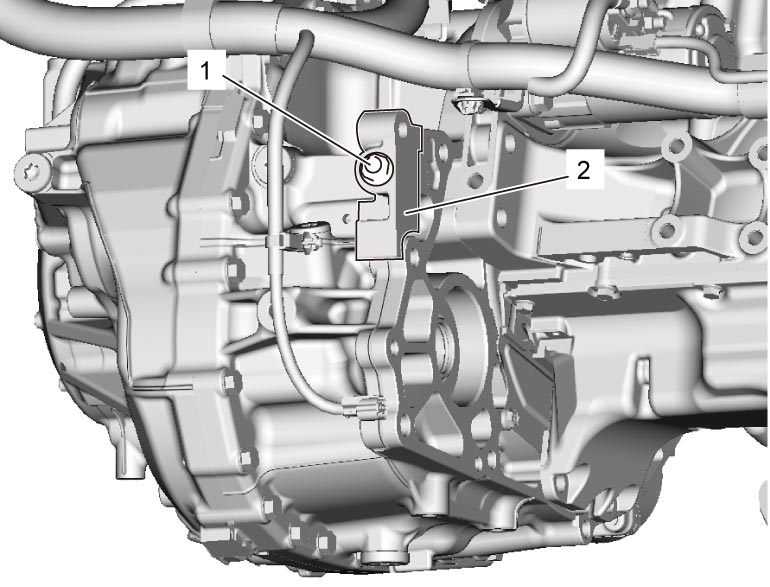
| 2. | Transmission and transfer stiffener |
b)Install transfer assembly.
c)Tighten transmission and transfer stiffener bolt to specified torque, if removed.
9)For 4WD model, install propeller shaft.
10)Install front drive shaft assembly.
11)Install exhaust No.1 pipe.
12)Tighten battery ground cable bolt (1) to specified torque.
13)Connect select cable.
14)Install ATF cooler pipe (1) and tighten ATF cooler pipe bolts (2) to specified torque.
15)Install ATF cooler hoses (3).
16)Connect radiator outlet hose (4) to radiator.
17)Connect TCM connector and each clamp.
18)Refill cooling system with coolant.
19)Install battery and battery bracket.
20)Refill A/T assembly with ATF, if necessary.
21)Check ATF level, if necessary.
22)Install left front fender lining.
23)Install engine undercover.
24)Perform TCM Learning Value Clearance, if A/T assembly is replaced.
25)Perform Neutral Position Calibration, if A/T assembly is replaced.
26)Perform TCM Learning Value Initialization, if A/T assembly is replaced.