NETWORKING CAN COMMUNICATION SYSTEM Short to B+ in CAN Bus Line
DESCRIPTION
There may be a short circuit between the CAN bus line and +B when the resistance between terminals 6 (CANH) and 16 (BAT) or terminals 14 (CANL) and 16 (BAT) of the DLC3 is below 6 kΩ.
| Symptom | Trouble Area |
|---|---|
| The resistance between terminals 6 (CANH) and 16 (BAT) or terminals 14 (CANL) and 16 (BAT) of the DLC3 is below 6 kΩ. | ·
Short between CAN bus lines and +B ·
Combination meter assembly ·
Master cylinder solenoid (skid control ECU) ·
Main body ECU (multiplex network body ECU) ·
Center airbag sensor assembly ·
Spiral cable sub-assembly (steering angle sensor) ·
Four wheel drive control ECU* ·
Yaw rate sensor assembly ·
Power steering ECU assembly ·
Air conditioning amplifier assembly ·
ECM ·
No. 1 junction connector ·
No. 2 junction connector ·
No. 3 junction connector |
*: for 4WD
WIRING DIAGRAM
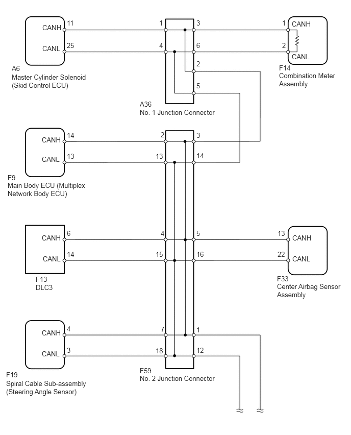
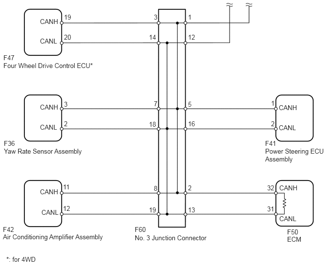
CAUTION / NOTICE / HINT
- HINT:
-
Operating the ignition switch, any switches or any doors triggers related ECU and sensor communication with the CAN, which causes resistance variation.
PROCEDURE
Disconnect the cable from the negative (-) battery terminal before measuring the resistances of the main wire and branch wire.
- CAUTION:
-
Wait at least 90 seconds after disconnecting the cable from the negative (-) battery terminal to disable the SRS system.
- NOTICE:
-
When disconnecting the cable, some systems need to be initialized after the cable is reconnected (See page General>INTRODUCTION>REPAIR INSTRUCTION>INITIALIZATION).
NEXT
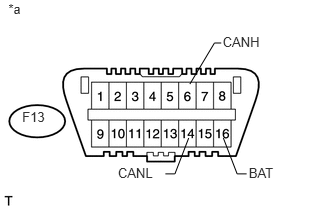
Disconnect the F59 No. 2 junction connector connector.
Measure the resistance according to the value(s) in the table below.
- Standard Resistance:
Tester Connection Switch Condition Specified Condition F13-6 (CANH) - F13-16 (BAT) Ignition switch off 6 kΩ or higher F13-14 (CANL) - F13-16 (BAT) Ignition switch off 6 kΩ or higher
| *a | Front view of DLC3 |
OK
NG
Reconnect the F59 No. 2 junction connector connector.
NEXT
Disconnect the A36 No. 1 junction connector connector.
Measure the resistance according to the value(s) in the table below.
- Standard Resistance:
Tester Connection Switch Condition Specified Condition F13-6 (CANH) - F13-16 (BAT) Ignition switch off 6 kΩ or higher F13-14 (CANL) - F13-16 (BAT) Ignition switch off 6 kΩ or higher
| *a | Front view of DLC3 |
OK
NG
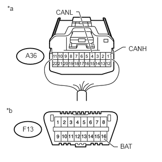
Measure the resistance according to the value(s) in the table below.
- Standard Resistance:
Tester Connection Switch Condition Specified Condition A36-1 (CANH) - F13-16 (BAT) Ignition switch off 6 kΩ or higher A36-4 (CANL) - F13-16 (BAT) Ignition switch off 6 kΩ or higher
| *a | Rear view of wire harness connector
(to No. 1 Junction Connector) |
| *b | Front view of DLC3 |
OK
NG
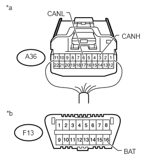
Measure the resistance according to the value(s) in the table below.
- Standard Resistance:
Tester Connection Switch Condition Specified Condition A36-3 (CANH) - F13-16 (BAT) Ignition switch off 6 kΩ or higher A36-6 (CANL) - F13-16 (BAT) Ignition switch off 6 kΩ or higher
| *a | Rear view of wire harness connector
(to No. 1 Junction Connector) |
| *b | Front view of DLC3 |
OK
NG
Reconnect the A36 No. 1 junction connector connector.
NEXT
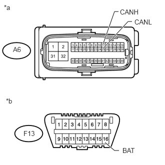
Disconnect the A6 master cylinder solenoid (skid control ECU) connector.
Measure the resistance according to the value(s) in the table below.
- Standard Resistance:
Tester Connection Switch Condition Specified Condition A6-11 (CANH) - F13-16 (BAT) Ignition switch off 6 kΩ or higher A6-25 (CANL) - F13-16 (BAT) Ignition switch off 6 kΩ or higher
| *a | Front view of wire harness connector
(to Master Cylinder Solenoid [Skid Control ECU]) |
| *b | Front view of DLC3 |
OK
NG
Reconnect the A36 No. 1 junction connector connector.
NEXT
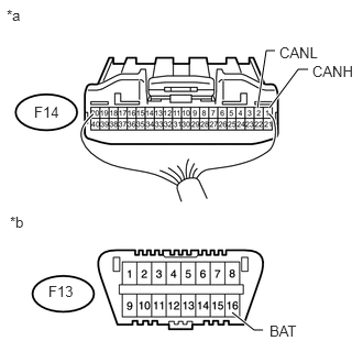
Disconnect the F14 combination meter assembly connector.
Measure the resistance according to the value(s) in the table below.
- Standard Resistance:
Tester Connection Switch Condition Specified Condition F14-1 (CANH) - F13-16 (BAT) Ignition switch off 6 kΩ or higher F14-2 (CANL) - F13-16 (BAT) Ignition switch off 6 kΩ or higher
| *a | Rear view of wire harness connector
(to Combination Meter Assembly) |
| *b | Front view of DLC3 |
OK
NG
Reconnect the A36 No. 1 junction connector connector.
NEXT
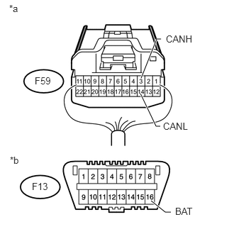
Disconnect the F59 No. 2 junction connector connector.
Measure the resistance according to the value(s) in the table below.
- Standard Resistance:
Tester Connection Switch Condition Specified Condition F59-3 (CANH) - F13-16 (BAT) Ignition switch off 6 kΩ or higher F59-14 (CANL) - F13-16 (BAT) Ignition switch off 6 kΩ or higher
| *a | Rear view of wire harness connector
(to No. 2 Junction Connector) |
| *b | Front view of DLC3 |
OK
NG
Reconnect the F59 No. 2 junction connector connector.
NEXT
Disconnect the F60 No. 3 junction connector connector.
Measure the resistance according to the value(s) in the table below.
- Standard Resistance:
Tester Connection Switch Condition Specified Condition F13-6 (CANH) - F13-16 (BAT) Ignition switch off 6 kΩ or higher F13-14 (CANL) - F13-16 (BAT) Ignition switch off 6 kΩ or higher
| *a | Front view of DLC3 |
OK
NG
- HINT:
-
For vehicles without four wheel drive, go to "Check for Short to B+ in CAN Bus Wire (No. 3 Junction connector - Power Steering ECU)".
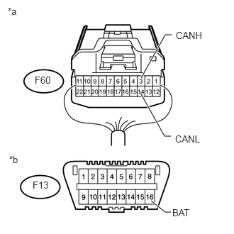
Measure the resistance according to the value(s) in the table below.
- Standard Resistance:
Tester Connection Switch Condition Specified Condition F60-3 (CANH) - F13-16 (BAT) Ignition switch off 6 kΩ or higher F60-14 (CANL) - F13-16 (BAT) Ignition switch off 6 kΩ or higher
| *a | Rear view of wire harness connector
(to No. 3 Junction Connector) |
| *b | Front view of DLC3 |
OK
NG
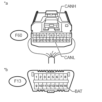
Measure the resistance according to the value(s) in the table below.
- Standard Resistance:
Tester Connection Switch Condition Specified Condition F60-5 (CANH) - F13-16 (BAT) Ignition switch off 6 kΩ or higher F60-16 (CANL) - F13-16 (BAT) Ignition switch off 6 kΩ or higher
| *a | Rear view of wire harness connector
(to No. 3 Junction Connector) |
| *b | Front view of DLC3 |
OK
NG
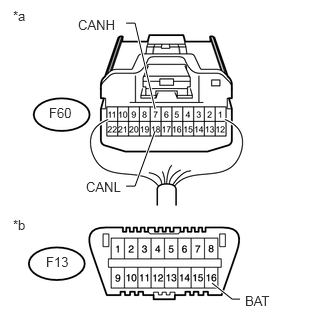
Measure the resistance according to the value(s) in the table below.
- Standard Resistance:
Tester Connection Switch Condition Specified Condition F60-7 (CANH) - F13-16 (BAT) Ignition switch off 6 kΩ or higher F60-18 (CANL) - F13-16 (BAT) Ignition switch off 6 kΩ or higher
| *a | Rear view of wire harness connector
(to No. 3 Junction Connector) |
| *b | Front view of DLC3 |
OK
NG
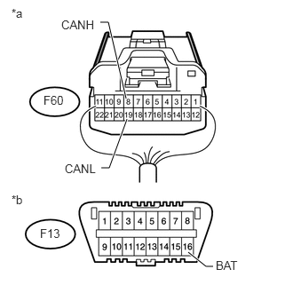
Measure the resistance according to the value(s) in the table below.
- Standard Resistance:
Tester Connection Switch Condition Specified Condition F60-8 (CANH) - F13-16 (BAT) Ignition switch off 6 kΩ or higher F60-19 (CANL) - F13-16 (BAT) Ignition switch off 6 kΩ or higher
| *a | Rear view of wire harness connector
(to No. 3 Junction Connector) |
| *b | Front view of DLC3 |
OK
NG
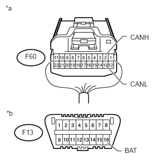
Measure the resistance according to the value(s) in the table below.
- Standard Resistance:
Tester Connection Switch Condition Specified Condition F60-2 (CANH) - F13-16 (BAT) Ignition switch off 6 kΩ or higher F60-13 (CANL) - F13-16 (BAT) Ignition switch off 6 kΩ or higher
| *a | Rear view of wire harness connector
(to No. 3 Junction Connector) |
| *b | Front view of DLC3 |
OK
NG
Reconnect the F60 No. 3 junction connector connector.
NEXT
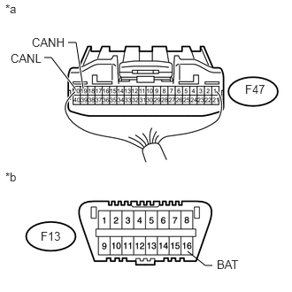
Disconnect the F47 four wheel drive control ECU connector.
Measure the resistance according to the value(s) in the table below.
- Standard Resistance:
Tester Connection Switch Condition Specified Condition F47-19 (CANH) - F13-16 (BAT) Ignition switch off 6 kΩ or higher F47-20 (CANL) - F13-16 (BAT) Ignition switch off 6 kΩ or higher
| *a | Rear view of wire harness connector
(to Four Wheel Drive Control ECU) |
| *b | Front view of DLC3 |
OK
NG
Reconnect the F60 No. 3 junction connector connector.
NEXT
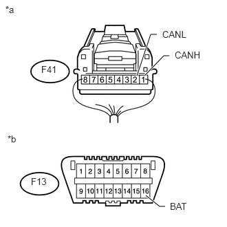
Disconnect the F41 power steering ECU assembly connector.
Measure the resistance according to the value(s) in the table below.
- Standard Resistance:
Tester Connection Switch Condition Specified Condition F41-1 (CANH) - F13-16 (BAT) Ignition switch off 6 kΩ or higher F41-2 (CANL) - F13-16 (BAT) Ignition switch off 6 kΩ or higher
| *a | Rear view of wire harness connector
(to Power Steering ECU Assembly) |
| *b | Front view of DLC3 |
OK
NG
Reconnect the F60 No. 3 junction connector connector.
NEXT
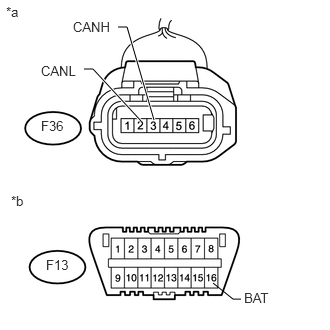
Disconnect the F36 yaw rate sensor assembly connector.
Measure the resistance according to the value(s) in the table below.
- Standard Resistance:
Tester Connection Switch Condition Specified Condition F36-3 (CANH) - F13-16 (BAT) Ignition switch off 6 kΩ or higher F36-2 (CANL) - F13-16 (BAT) Ignition switch off 6 kΩ or higher
| *a | Front view of wire harness connector
(to Yaw Rate Sensor Assembly) |
| *b | Front view of DLC3 |
OK
NG
Reconnect the F60 No. 3 junction connector connector.
NEXT
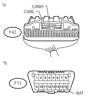
Disconnect the F42 air conditioning amplifier assembly connector.
Measure the resistance according to the value(s) in the table below.
- Standard Resistance:
Tester Connection Switch Condition Specified Condition F42-11 (CANH) - F13-16 (BAT) Ignition switch off 6 kΩ or higher F42-12 (CANL) - F13-16 (BAT) Ignition switch off 6 kΩ or higher
| *a | Rear view of wire harness connector
(to Air Conditioning Amplifier Assembly) |
| *b | Front view of DLC3 |
OK
NG
Reconnect the F60 No. 3 junction connector connector.
NEXT
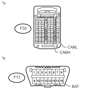
Disconnect the F50 ECM connector.
Measure the resistance according to the value(s) in the table below.
- Standard Resistance:
Tester Connection Switch Condition Specified Condition F50-32 (CANH) - F13-16 (BAT) Ignition switch off 6 kΩ or higher F50-31 (CANL) - F13-16 (BAT) Ignition switch off 6 kΩ or higher
| *a | Rear view of wire harness connector
(to ECM) |
| *b | Front view of DLC3 |
OK
NG
Reconnect the F60 No. 3 junction connector connector.
NEXT
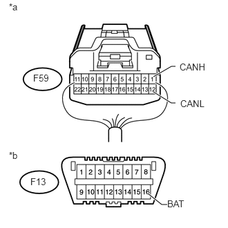
Disconnect the F59 No. 2 junction connector connector.
Measure the resistance according to the value(s) in the table below.
- Standard Resistance:
Tester Connection Switch Condition Specified Condition F59-1 (CANH) - F13-16 (BAT) Ignition switch off 6 kΩ or higher F59-12 (CANL) - F13-16 (BAT) Ignition switch off 6 kΩ or higher
| *a | Rear view of wire harness connector
(to No. 2 Junction Connector) |
| *b | Front view of DLC3 |
OK
NG
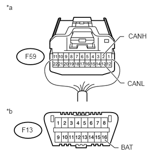
Measure the resistance according to the value(s) in the table below.
- Standard Resistance:
Tester Connection Switch Condition Specified Condition F59-2 (CANH) - F13-16 (BAT) Ignition switch off 6 kΩ or higher F59-13 (CANL) - F13-16 (BAT) Ignition switch off 6 kΩ or higher
| *a | Rear view of wire harness connector
(to No. 2 Junction Connector) |
| *b | Front view of DLC3 |
OK
NG
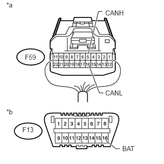
Measure the resistance according to the value(s) in the table below.
- Standard Resistance:
Tester Connection Switch Condition Specified Condition F59-5 (CANH) - F13-16 (BAT) Ignition switch off 6 kΩ or higher F59-16 (CANL) - F13-16 (BAT) Ignition switch off 6 kΩ or higher
| *a | Rear view of wire harness connector
(to No. 2 Junction Connector) |
| *b | Front view of DLC3 |
OK
NG
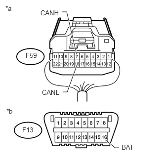
Measure the resistance according to the value(s) in the table below.
- Standard Resistance:
Tester Connection Switch Condition Specified Condition F59-7 (CANH) - F13-16 (BAT) Ignition switch off 6 kΩ or higher F59-18 (CANL) - F13-16 (BAT) Ignition switch off 6 kΩ or higher
| *a | Rear view of wire harness connector
(to No. 2 Junction Connector) |
| *b | Front view of DLC3 |
OK
NG
Reconnect the F59 No. 2 junction connector connector.
NEXT
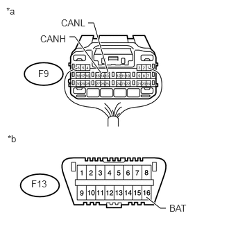
Disconnect the F9 main body ECU (multiplex network body ECU) connector.
Measure the resistance according to the value(s) in the table below.
- Standard Resistance:
Tester Connection Switch Condition Specified Condition F9-14 (CANH) - F13-16 (BAT) Ignition switch off 6 kΩ or higher F9-13 (CANL) - F13-16 (BAT) Ignition switch off 6 kΩ or higher
| *a | Rear view of wire harness connector
(to Main Body ECU [Multiplex Network Body ECU]) |
| *b | Front view of DLC3 |
OK
NG
Reconnect the F59 No. 2 junction connector connector.
NEXT
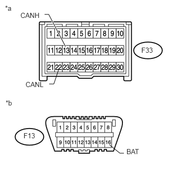
Disconnect the F33 center airbag sensor assembly connector.
Measure the resistance according to the value(s) in the table below.
- Standard Resistance:
Tester Connection Switch Condition Specified Condition F33-13 (CANH) - F13-16 (BAT) Ignition switch off 6 kΩ or higher F33-22 (CANL) - F13-16 (BAT) Ignition switch off 6 kΩ or higher
| *a | Front view of wire harness connector
(to Center Airbag Sensor Assembly) |
| *b | Front view of DLC3 |
OK
NG
Reconnect the F59 No. 2 junction connector connector.
NEXT
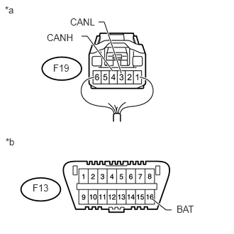
Disconnect the F19 spiral cable sub-assembly (steering angle sensor) connector.
Measure the resistance according to the value(s) in the table below.
- Standard Resistance:
Tester Connection Switch Condition Specified Condition F19-4 (CANH) - F13-16 (BAT) Ignition switch off 6 kΩ or higher F19-3 (CANL) - F13-16 (BAT) Ignition switch off 6 kΩ or higher
| *a | Rear view of wire harness connector
(to Spiral Cable Sub-assembly [Steering Angle Sensor]) |
| *b | Front view of DLC3 |
OK
NG