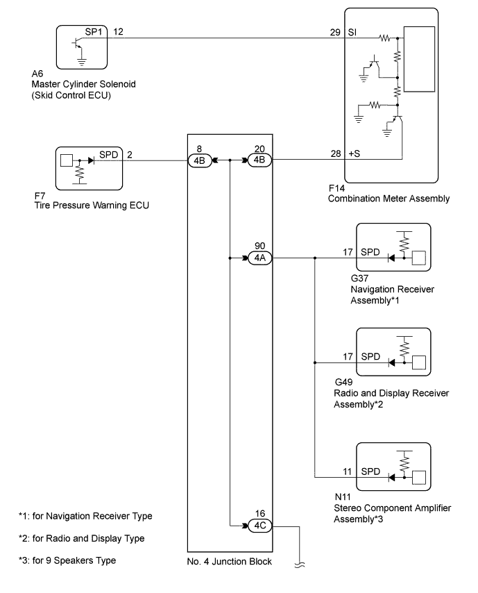
METER / GAUGE SYSTEM > Speed Signal Circuit |
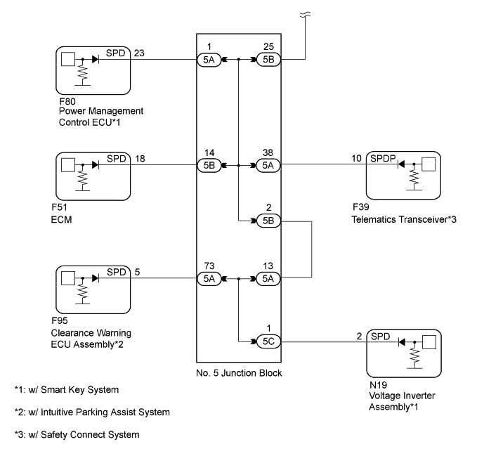
| 1.CHECK ECU TERMINAL VOLTAGE (INPUT VOLTAGE) |
 |
Disconnect the F14 combination meter assembly connector.
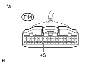
Measure the voltage according to the value(s) in the table below.
| Tester Connection | Switch Condition | Specified Condition |
| F14-28 (+S) - Body ground | Ignition switch ON | 4.5 to 14 V |
| *a | Front view of wire harness connector (to Combination Meter Assembly) |
|
| ||||
| OK | |
 |
| 2.CHECK COMBINATION METER ASSEMBLY (OUTPUT VOLTAGE) |
 |
Disconnect the A6 master cylinder solenoid (skid control ECU) connector.
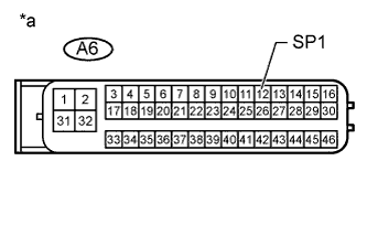
Measure the voltage according to the value(s) in the table below.
| Tester Connection | Switch Condition | Specified Condition |
| A6-12 (SP1) - Body ground | Ignition switch ON | 11 to 14 V |
| *a | Front view of wire harness connector (to Master Cylinder Solenoid (Skid Control ECU)) |
|
| ||||
| OK | |
|
| 3.CHECK COMBINATION METER ASSEMBLY (SPEED SIGNAL) |
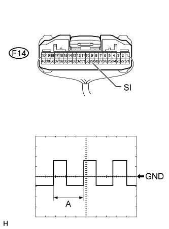 |
Check the input waveform.
Reconnect the F14 combination meter assembly connector.
Remove the combination meter assembly with the connector(s) still connected.
Connect an oscilloscope to terminal F14-29 (SI) and body ground.
Turn the ignition switch to ON.
Check the signal waveform according to the condition(s) in the table below.
| Item | Condition |
| Terminal No. (Symbol) | F14-29 (SI) - Body ground |
| Tool setting | 5 V/DIV., 20 ms./DIV. |
| Condition | Driving at approx. 20 km/h (12 mph) |
|
| ||||
| OK | ||
 | ||
| ||
| 4.CHECK HARNESS AND CONNECTOR (COMBINATION METER ASSEMBLY - MASTER CYLINDER SOLENOID) |
Disconnect the F14 combination meter assembly connector.
Disconnect the A6 master cylinder solenoid (skid control ECU ) connector.
Measure the resistance according to the value(s) in the table below.
| Tester Connection | Condition | Specified Condition |
| F14-29 (SI) - A6-12 (SP1) | Always | Below 1 Ω |
| A6-12 (SP1) - Body ground | Always | 10 kΩ or higher |
|
| ||||
| OK | ||
| ||
| ||
| 5.CHECK HARNESS AND CONNECTOR (COMBINATION METER ASSEMBLY - NO. 4 JUNCTION BLOCK) |
Disconnect the F14 combination meter assembly connector.
Disconnect the 4B No.4 junction block connector.
Measure the resistance according to the value(s) in the table below.
| Tester Connection | Condition | Specified Condition |
| F14-28 (+S) - 4B-20 | Always | Below 1 Ω |
| F14-28 (+S) - Body ground | Always | 10 kΩ or higher |
|
| ||||
| OK | |
|
| 6.CHECK HARNESS AND CONNECTOR (NO. 4 JUNCTION BLOCK) |
Inspect for a short in the circuit that is connected to the junction block connector shown in the wiring diagram.
Disconnect the 4A No.4 junction block connector.
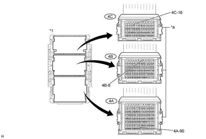
| *1 | No. 4 Junction Block | - | - |
| *a | Front view of wire harness connector (to No. 4 Junction Block) | - | - |
Disconnect the 4C No.4 junction block connector.
Measure the voltage according to the value(s) in the table below.
| Tester Connection | Switch Condition | Specified Condition |
| 4C-16 - Body ground | Ignition switch ON | 4.5 to 14 V |
| 4B-8 - Body ground | Ignition switch ON | 4.5 to 14 V |
| 4A-90 - Body ground | Ignition switch ON | 4.5 to 14 V |
| Result | Proceed to |
| Voltage is not present in one circuit | A |
| Voltage is present in all the circuits | B |
|
| ||||
| A | |
|
| 7.SYSTEM CHECK |
Select the circuit for which voltage was not present in the previous step.
| Tester Connection | System that Uses the Circuit | Proceed to |
| 4C-16 - Body ground | SFI system, smart key system*1, safety connect system*2, voltage inverter*1, intuitive parking assist system*3 | A |
| 4B-8 - Body ground | Tire pressure warning system | B |
| 4A-90 - Body ground | Audio and visual system or navigation system | C |
|
| ||||
|
| ||||
| A | |
|
| 8.CHECK HARNESS AND CONNECTOR (NO. 4 JUNCTION BLOCK - NO. 5 JUNCTION BLOCK) |
Disconnect the 4C No.4 junction block connector.
Disconnect the 5B No.5 junction block connector.
Measure the resistance according to the value(s) in the table below.
| Tester Connection | Condition | Specified Condition |
| 4C-16 - 5B-25 | Always | Below 1 Ω |
| 4C-16 - Body ground | Always | 10 kΩ or higher |
|
| ||||
| OK | |
|
| 9.CHECK HARNESS AND CONNECTOR (NO. 5 JUNCTION BLOCK) |
Disconnect the 5A No.5 junction block connector.
Measure the resistance according to the value(s) in the table below.
| Tester Connection | Condition | Specified Condition |
| 5B-2 - 5A-13 | Always | Below 1 Ω |
| 5B-2 - Body ground | Always | 10 kΩ or higher |
|
| ||||
| OK | |
|
| 10.CHECK HARNESS AND CONNECTOR (NO. 5 JUNCTION BLOCK) |
Inspect for a short in the circuit that is connected to the junction block connector shown in the wiring diagram.
Disconnect the 5C No.5 junction block connector.
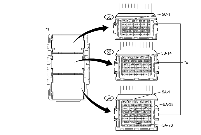
| *1 | No. 5 Junction Block | - | - |
| *a | Front view of wire harness connector (to No. 5 Junction Block) | - | - |
Measure the voltage according to the value(s) in the table below.
| Tester Connection | Switch Condition | Specified Condition |
| 5B-14 - Body ground | Ignition switch ON | 4.5 to 14 V |
| 5C-1 - Body ground*1 | Ignition switch ON | 4.5 to 14 V |
| 5A-1 - Body ground*1 | Ignition switch ON | 4.5 to 14 V |
| 5A-38 - Body ground*2 | Ignition switch ON | 4.5 to 14 V |
| 5A-73 - Body ground*3 | Ignition switch ON | 4.5 to 14 V |
| Result | Proceed to |
| Voltage is not present in one circuit | A |
| Voltage is present in all the circuits | B |
|
| ||||
| A | |
|
| 11.SYSTEM CHECK |
Select the circuit for which voltage was not present in the previous step.
| Tester Connection | System that Uses the Circuit | Proceed to |
| 5B-14 - Body ground | SFI system | A |
| 5C-1 - Body ground*1 | Voltage inverter | B |
| 5A-1 - Body ground*1 | Smart key system | C |
| 5A-38 - Body ground*2 | Safety connect system | D |
| 5A-73 - Body ground*3 | Intuitive Parking Assist System | E |
|
| ||||
|
| ||||
|
| ||||
|
| ||||
| A | |
|
| 12.CHECK HARNESS AND CONNECTOR (ECM CIRCUIT) |
Disconnect the F51 ECM connector.
Measure the resistance according to the value(s) in the table below.
| Tester Connection | Condition | Specified Condition |
| F51-18 (SPD) - Body ground | Always | 10 kΩ or higher |
|
| ||||
| OK | ||
| ||
| ||
| 13.CHECK HARNESS AND CONNECTOR (VOLTAGE INVERTER ASSEMBLY CIRCUIT) |
Disconnect the N19 voltage inverter assembly connector.
Measure the resistance according to the value(s) in the table below.
| Tester Connection | Condition | Specified Condition |
| N19-2 (SPD) - Body ground | Always | 10 kΩ or higher |
|
| ||||
| OK | ||
| ||
| ||
| 14.CHECK HARNESS AND CONNECTOR (POWER MANAGEMENT CONTROL ECU CIRCUIT) |
Disconnect the F80 power management control ECU connector.
Measure the resistance according to the value(s) in the table below.
| Tester Connection | Condition | Specified Condition |
| F80-23 (SPD) - Body ground | Always | 10 kΩ or higher |
|
| ||||
| OK | ||
| ||
| ||
| 15.CHECK HARNESS AND CONNECTOR (TELEMATICS TRANSCEIVER CIRCUIT) |
Disconnect the F39 telematics transceiver connector.
Measure the resistance according to the value(s) in the table below.
| Tester Connection | Condition | Specified Condition |
| F39-10 (SPDP) - Body ground | Always | 10 kΩ or higher |
|
| ||||
| OK | ||
| ||
| ||
| 16.CHECK HARNESS AND CONNECTOR (TIRE PRESSURE WARNING ECU CIRCUIT) |
Disconnect the F7 tire pressure warning ECU connector.
Measure the resistance according to the value(s) in the table below.
| Tester Connection | Condition | Specified Condition |
| F7-2 (SPD) - Body ground | Always | 10 kΩ or higher |
|
| ||||
| OK | ||
| ||
| ||
| 17.SYSTEM CHECK |
Proceed to the appropriate inspection based on the components of the vehicle.
| Component | Proceed to |
| for Navigation Receiver Type | A |
| for Radio and Display Type | B |
| for 9 Speakers Type | C |
|
| ||||
|
| ||||
| A | |
|
| 18.CHECK HARNESS AND CONNECTOR (NAVIGATION RECEIVER CIRCUIT) |
Disconnect the G37 navigation receiver connector.
Measure the voltage according to the value(s) in the table below.
| Tester Connection | Switch Condition | Specified Condition |
| G37-17 (SPD) - Body ground | Always | 10 kΩ or higher |
|
| ||||
| OK | ||
| ||
| ||
| 19.CHECK HARNESS AND CONNECTOR (RADIO AND DISPLAY RECEIVER CIRCUIT) |
Disconnect the G49 radio and display receiver connector.
Measure the voltage according to the value(s) in the table below.
| Tester Connection | Switch Condition | Specified Condition |
| G49-17 (SPD) - Body ground | Always | 10 kΩ or higher |
|
| ||||
| OK | ||
| ||
| ||
| 20.CHECK HARNESS AND CONNECTOR (CLEARANCE WARNING ECU CIRCUIT) |
Disconnect the F95 clearance warning ECU connector.
Measure the resistance according to the value(s) in the table below.
| Tester Connection | Condition | Specified Condition |
| F95-5 (SPD) - Body ground | Always | 10 kΩ or higher |
|
| ||||
| OK | ||
| ||
| ||
| 21.CHECK HARNESS AND CONNECTOR (STEREO COMPONENT AMPLIFIER ASSEMBLY) |
Disconnect the N11 stereo component amplifier connector.
Measure the resistance according to the value(s) in the table below.
| Tester Connection | Condition | Specified Condition |
| N11-11 (SPD) - Body ground | Always | 10 kΩ or higher |
|
| ||||
| OK | ||
| ||
| ||

