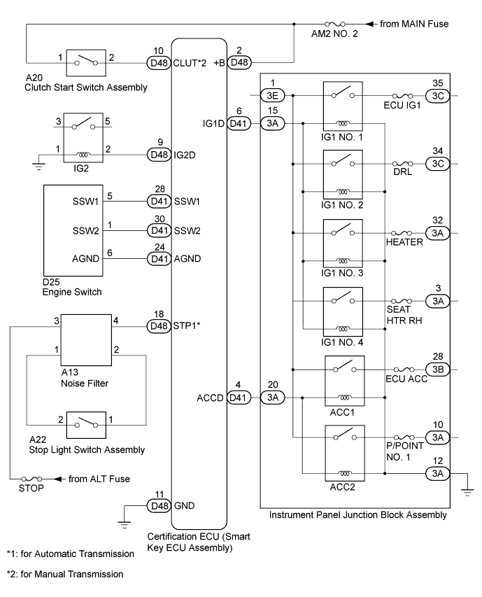
ENTRY AND START SYSTEM (for Start Function) > Power Source Mode does not Change to ON (IG and ACC) |
| Problem Symptom | Data List Item | Active Test Item |
| Power source mode does not change to on (IG) or on (ACC) | Power Source Control
Engine
| - |
| 1.CHECK WIRELESS DOOR LOCK CONTROL SYSTEM (OPERATION) |
Check that the wireless door lock function operates normally (Click here).
|
| ||||
| OK | |
 |
| 2.CHECK HARNESS AND CONNECTOR (POWER SOURCE) |
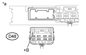 |
Disconnect the D48 certification ECU (smart key ECU assembly) connector.
Measure the voltage according to the value(s) in the table below.
| Tester Connection | Condition | Specified Condition |
| D48-2 (+B) - Body ground | Always | 9.5 to 16 V |
| *a | Rear view of harness connected (to Certification ECU (Smart Key ECU Assembly)) |
|
| ||||
| OK | |
|
| 3.CHECK HARNESS AND CONNECTOR (GROUND) |
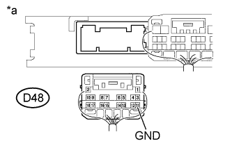 |
Measure the resistance according to the value(s) in the table below.
| Tester Connection | Condition | Specified Condition |
| D48-11 (GND) - Body ground | Always | Below 1 Ω |
| *a | Rear view of harness connected (to Certification ECU (Smart Key ECU Assembly)) |
|
| ||||
| OK | |
|
| 4.CHECK ENTRY AND START SYSTEM |
Remove the battery of the electrical key transmitter sub-assembly (Click here).
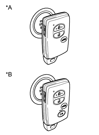 |
With the brake pedal*1 or clutch pedal*2 depressed, hold the electrical key transmitter sub-assembly touch the engine switch while facing the logo side of the electrical key transmitter sub-assembly to the engine switch.
When touch the logo of the electrical key transmitter sub-assembly to the engine switch, check whether the power source mode changes.
| Result | Proceed to |
| NG (Power source mode does not change) | A |
| OK (Power source mode changes) | B |
| *A | w/o Panic Switch |
| *B | w/ Panic Switch |
|
| ||||
| A | |
|
| 5.READ VALUE USING GTS (STOP LIGHT SWITCH, NEUTRAL SW/CLUTCH SW) |
for Automatic Transmission
Connect the GTS to the DLC3.
Turn the engine switch on (IG).
Turn the GTS on.
Enter the following menus: Body Electrical / Power Source Control / Data List.
According to the display on the GTS tester, read the Data List.
| Tester Display | Measurement Item/Range | Normal Condition | Diagnostic Note |
| Stop Light Switch1 | State of brake pedal / OFF or ON | OFF: Brake pedal released ON: Brake pedal depressed |
|
for Manual Transmission
Connect the GTS to the DLC3.
Turn the engine switch on (IG).
Turn the GTS on.
Enter the following menus: Body Electrical / Power Source Control / Data List.
According to the display on the GTS, read the Data List.
| Tester Display | Measurement Item/Range | Normal Condition | Diagnostic Note |
| Neutral SW / Clutch SW | State of clutch pedal / OFF or ON | OFF: Clutch pedal released ON: Clutch pedal depressed |
|
| Result | Proceed to |
| OK | A |
| NG (for Automatic Transmission) | B |
| NG (for Manual Transmission) | C |
|
| ||||
|
| ||||
| A | |
|
| 6.READ VALUE USING GTS (POWER SUPPLY CONDITION) |
Connect the GTS to the DLC3.
Turn the engine switch on (IG).
Turn the GTS on.
Enter the following menus: Body Electrical / Power Source Control / Data List.
According to the display on the GTS, read the Data List.
| Tester Display | Measurement Item/Range | Normal Condition | Diagnostic Note |
| Power Supply Condition | Power Supply Condition / All OFF, IG1 ON or ACC ON, IG2 ON, ST ON, | All OFF: Engine switch off (ACC and IG) ACC ON: Engine switch on (ACC)) IG1 ON: Engine switch on (IG) (IG1 relay on) IG2 ON: Engine switch on (IG) (IG2 relay on) ST ON: Sending engine start request signal | Since IG1 ON and IG2 ON turn on at approximately the same time, IG1 ON may not be displayed (IG1 ON turns on for a very short time). |
|
| ||||
| OK | |
|
| 7.INSPECT CERTIFICATION ECU (SMART KEY ECU ASSEMBLY) |
Connect the GTS to the DLC3.
Turn the engine switch on (IG).
Turn the GTS on.
Enter the following menus: Body Electrical / Power Source Control / Data List.
According to the display on the GTS, read the Data List.
| Tester Display | Measurement Item/Range | Normal Condition | Diagnostic Note |
| Power Supply Condition | Power Supply Condition / All OFF, IG ON or ACC ON, IG2 ON, ST ON, | All OFF: Engine switch off (ACC and IG) ACC ON: Engine switch on (ACC)) IG1 ON: Engine switch on (IG) (IG1 relay on) IG2 ON: Engine switch on (IG) (IG2 relay on) ST ON: Sending engine start request signal | Since IG1 ON and IG2 ON turn on at approximately the same time, IG1 ON may not be displayed (IG1 ON turns on for a very short time). |
Measure the voltage according to the value(s) in the table below.
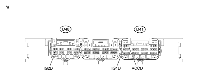
| *a | Component with harness connected (Certification ECU (Smart Key ECU Assembly)) | - | - |
| Tester Connection | Switch Condition | Specified Condition |
| D41-6 (IG1D) - Body ground | Engine switch off | 1 V or less |
| Engine switch on (ACC) | 1 V or less | |
| Engine switch on (IG) | 9 V or higher | |
| D48-9 (IG2D) - Body ground | Engine switch off | 1 V or less |
| Engine switch on (ACC) | 1 V or less | |
| Engine switch on (IG) | 9 V or higher | |
| D41-4 (ACCD) - Body ground | Engine switch off | 1 V or less |
| Engine switch on (ACC) | 8.5 V or higher | |
| Engine switch on (IG) | 8.5 V or higher |
|
| ||||
| OK | ||
 | ||
| ||
| 8.INSPECT STOP LIGHT SWITCH ASSEMBLY |
Remove the stop light switch assembly (Click here).
Inspect the stop light switch assembly (Click here).
|
| ||||
| OK | |
|
| 9.CHECK HARNESS AND CONNECTOR (NOISE FILTER - CERTIFICATION ECU (SMART KEY ECU ASSEMBLY)) |
Disconnect the D48 certification ECU (smart key ECU assembly) connector.
Disconnect the A13 noise filter connector.
Measure the resistance according to the value(s) in the table below.
| Tester Connection | Condition | Specified Condition |
| D48-18 (STP1) - A13-4 | Always | Below 1 Ω |
| D48-18 (STP1) - Body ground | Always | 10 kΩ or higher |
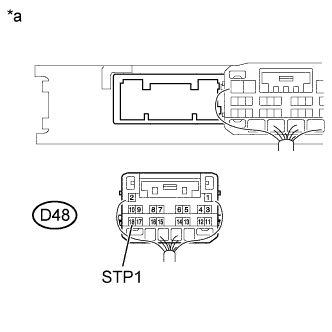 |
Reconnect the A13 noise filter connector.
Measure the voltage according to the value(s) in the table below.
| Tester Connection | Condition | Specified Condition |
| D48-18 (STP1) - Body ground | Brake pedal released | Below 1 V |
| Brake pedal depressed | 9 V or higher |
| *a | Rear view of wire harness connector (Certification ECU (Smart Key ECU Assembly)) |
|
| ||||
| OK | ||
| ||
| ||
| 10.INSPECT CLUTCH START SWITCH ASSEMBLY |
Remove the clutch start switch assembly.
Inspect the clutch start switch assembly.
| Result | Proceed to |
| OK | A |
| NG (for LHD) | B |
| NG (for RHD) | C |
|
| ||||
|
| ||||
| A | |
|
| 11.CHECK HARNESS AND CONNECTOR |
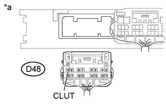 |
Disconnect the D48 certification ECU (smart key ECU assembly) connector.
Disconnect the A20 clutch start switch assembly connector.
Measure the resistance according to the value(s) in the table below.
| Tester Connection | Condition | Specified Condition |
| D48-10 (CLUT) - A20-1 | Always | Below 1 Ω |
| D48-10 (CLUT) - Body ground | Always | 10 kΩ or higher |
Reconnect the A20 clutch start switch assembly connector.
Measure the voltage according to the value(s) in the table below.
| Tester Connection | Condition | Specified Condition |
| D48-10 (CLUT) - Body ground | Clutch pedal released → clutch pedal depressed | Below 1 V → 9 V or higher |
| *a | Rear view of wire harness connector (to certification ECU (smart key ECU assembly)) |
|
| ||||
| OK | ||
| ||
| ||
| 12.CHECK FOR DTC |
Check the DTCs (Click here).
| Result | Proceed to |
| DTC is not output | A |
| DTC B2784 is output | B |
| DTC B2785 is output | C |
|
| ||||
|
| ||||
| A | ||
| ||
| ||
| 13.READ VALUE USING GTS (START SWITCH 1, 2) |
Connect the GTS to the DLC3.
Turn the engine switch on (IG).
Turn the GTS on.
Enter the following menus: Body Electrical / Power Source Control / Data List.
According to the display on the GTS, read the Data List.
| Tester Display | Measurement Item/Range | Normal Condition | Diagnostic Note |
| Start Switch 1 | Condition of engine switch contact 1 / OFF or ON | OFF: Engine switch not pushed ON: Engine switch pushed |
|
| Start Switch 2 | Condition of engine switch contact 2 / OFF or ON | OFF: Engine switch not pushed ON : Engine switch pushed |
|
| Result | Proceed to |
| NG | A |
| OK | B |
|
| ||||
| A | |
|
| 14.INSPECT ENGINE SWITCH |
Remove the engine switch (Click here).
Inspect the engine switch (Click here).
|
| ||||
| OK | |
|
| 15.CHECK HARNESS AND CONNECTOR (CERTIFICATION ECU (SMART KEY ECU ASSEMBLY) - ENGINE SWITCH) |
Disconnect the D41 certification ECU (smart key ECU assembly) connector.
Disconnect the D25 engine switch connector.
Measure the resistance according to the value(s) in the table below.
| Tester Connection | Condition | Specified Condition |
| D41-28 (SSW1) - D25-5 (SS1) | Always | Below 1 Ω |
| D41-30 (SSW2) - D25-1 (SS2) | Always | Below 1 Ω |
| D41-28 (SSW1) - Body ground | Always | 10 kΩ or higher |
| D41-30 (SSW2) - Body ground | Always | 10 kΩ or higher |
|
| ||||
| OK | ||
| ||
| ||

