 |
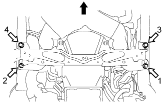
Tighten 4 new bolts in the order shown in the illustration, and temporarily install the front cross member sub-assembly.
 | Vehicle of Front Side |
 | Bolt |
FRONT SUSPENSION MEMBER > INSTALLATION |
| 1. INSTALL FRONT CROSS MEMBER SUB-ASSEMBLY |
|
Tighten 4 new bolts in the order shown in the illustration, and temporarily install the front cross member sub-assembly.
| Vehicle of Front Side |
| Bolt |
Tighten the 4 bolts.
| 2. ADJUST SHIFT LEVER POSITION (for Automatic Transmission) |
| 3. INSTALL RACK AND PINION POWER STEERING GEAR ASSEMBLY |
| 4. INSTALL REAR BODY MOUNTING CUSHION SUB-ASSEMBLY LH |
Install the rear body mounting cushion sub-assembly LH and front stabilizer bar with the 4 new bolts.
| 5. INSTALL REAR BODY MOUNTING CUSHION SUB-ASSEMBLY RH |
| 6. INSTALL FRONT STABILIZER LINK ASSEMBLY LH |
Install the front stabilizer link assembly to the front shock absorber assembly with a new nut.
Using a socket hexagon wrench 6 mm, fix the stud bolt and install the front stabilizer link assembly LH with a new nut.
| 7. INSTALL FRONT STABILIZER LINK ASSEMBLY RH |
| 8. INSTALL FRONT LOWER SUSPENSION ARM ASSEMBLY LH |
| 9. INSTALL FRONT LOWER SUSPENSION ARM ASSEMBLY RH |
| 10. INSTALL ENGINE ASSEMBLY |
| 11. INSPECT STEERING WHEEL CENTER POINT |
| 12. INSPECT AND ADJUST FRONT WHEEL ALIGNMENT |
| 13. VSC SENSOR NEUTRAL MEMORIZATION |
| 14. HEIGHT CONTROL SENSOR SIGNAL INITIALIZE (w/ HID Headlight System) |
| 15. ADJUST HEADLIGHT AIMING (w/ HID Headlight System) |