TL70 MANUAL TRANSMISSION / TRANSAXLE MANUAL TRANSMISSION ASSEMBLY REMOVAL
CAUTION / NOTICE / HINT
- NOTICE:
-
When removing the manual transmission assembly, be sure to remove and clean the clutch release fork sub-assembly.
-
Click hereDrivetrain>CLUTCH>CLUTCH UNIT>REMOVAL
PROCEDURE

 1.DISCONNECT CABLE FROM NEGATIVE BATTERY TERMINAL
51441
2.REMOVE NO. 1 ENGINE UNDER COVER
51442E
3.REMOVE NO. 2 ENGINE UNDER COVER
51444A
4.REMOVE REAR ENGINE UNDER COVER LH (w/ Floor Under Cover)
51443C
5.REMOVE REAR ENGINE UNDER COVER RH (w/ Floor Under Cover)
- HINT:
-
Use the same procedure for the RH side as for the LH side.
6.DRAIN MANUAL TRANSMISSION OIL
37100
7.REMOVE PROPELLER SHAFT WITH CENTER BEARING ASSEMBLY
48811
8.REMOVE FRONT STABILIZER BAR
28100
9.REMOVE STARTER ASSEMBLY
10.SEPARATE WIRE HARNESS
- HINT:
-
Fix the disconnected harness components with tape to keep them out of the way.
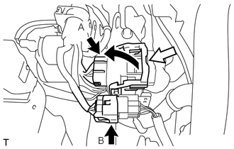
Release the lock of connector (A) and disconnect the connector.
Disconnect the connector (B).
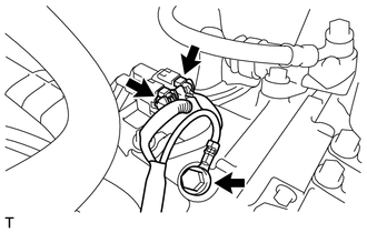
Disconnect the 2 connectors.
Remove the bolt and disconnect the ground cable.
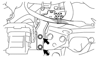
Disengage the wire harness clamp.
Remove the 2 bolts and the wire harness clamp bracket.
31470
11.SEPARATE CLUTCH RELEASE CYLINDER ASSEMBLY
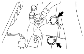
Remove the 2 bolts and separate the clutch release cylinder assembly.
12.SEPARATE MANUAL TRANSMISSION ASSEMBLY
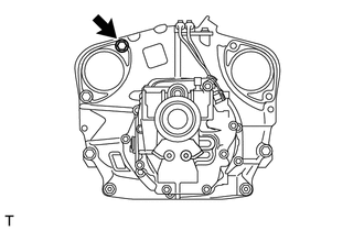
Remove the bolt from the manual transmission assembly.
17141
13.REMOVE EXHAUST MANIFOLD
14.SUPPORT ENGINE ASSEMBLY
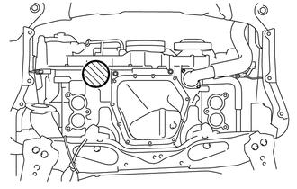
Support the engine assembly with an engine lifter so that it is stable, as shown in the illustration.

|
Attachment Placement Positions |
- NOTICE:
- ·
Set the engine assembly with transmission so that it is horizontal.
·Never attach the attachment and plate lift attachment to the oil pan section of the engine assembly.
33530F
15.DISCONNECT FLOOR SHIFT LEVER ASSEMBLY
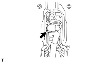
Turn over the shift and select lever boot.
Using a screwdriver, remove the clip and the floor shift lever assembly.
Remove the plate washer from the floor shift lever assembly.
Remove the 2 collars and O-ring from the floor shift lever assembly.
17455
16.REMOVE EXHAUST PIPE BRACKET
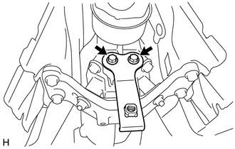
Remove the 2 bolts and the exhaust pipe bracket.
17.SUPPORT MANUAL TRANSMISSION ASSEMBLY
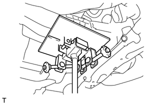
Support the manual transmission assembly with a transmission jack.
- NOTICE:
- ·
Check that the manual transmission assembly is centered on the transmission jack plate.
·When removing the manual transmission assembly, support the engine assembly so that it does not tilt.
12372
18.REMOVE REAR NO. 2 ENGINE MOUNTING INSULATOR
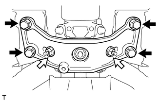
Remove the 4 bolts, 2 washers, 2 nuts and rear No. 2 engine mounting insulator.

|
Bolt |

|
Nut |
33575
19.DISCONNECT FLOOR SHIFT CONTROL SHIFT LEVER RETAINER
Tilt the manual transmission assembly.
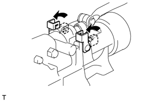
Pull up the locks of the shift lever pins, and remove the 2 shift lever pins.
Disconnect the floor shift control shift lever retainer.
33555B
20.REMOVE SHIFT AND SELECT LEVER BOOT
Remove the shift and select lever boot from the floor shift lever assembly.
21.REMOVE MANUAL TRANSMISSION ASSEMBLY
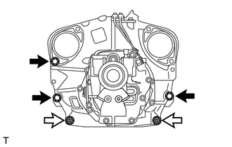
Remove the 3 bolts, 2 nuts and manual transmission assembly.
|
|
Bolt |
|
|
Nut |
- NOTICE:
- ·
Do not apply excessive force to the transmission assembly as this will break the input shaft.
·To prevent damage to the knock pins, do not pry between the manual transmission assembly and the engine assembly.
12371
22.REMOVE REAR NO. 1 ENGINE MOUNTING INSULATOR
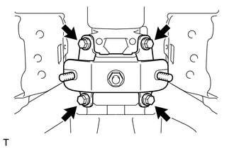
Remove the 4 bolts and rear No. 1 engine mounting insulator.
33511
23.REMOVE FLOOR SHIFT CONTROL SHAFT
33511G
24.REMOVE CONTROL SHAFT