1NR-VE LUBRICATION OIL PUMP INSTALLATION
PROCEDURE

 11302
1.INSTALL TIMING CHAIN COVER SUB-ASSEMBLY
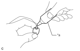
| *a | Adhesive 1324 |
Apply adhesive to 2 or 3 threads of the plug.
- Adhesive:
Toyota Genuine Adhesive 1324, Three Bond 1324 or equivalent
Using an 8 mm socket hexagon wrench, install the plug.
- Torque:
- 15 N*m (153 kgf*cm, 11 ft.*lbf)
- NOTICE:
- ·
Install the plug within 3 minutes of applying adhesive.
·Do not start the engine for at least 1 hour after installation.
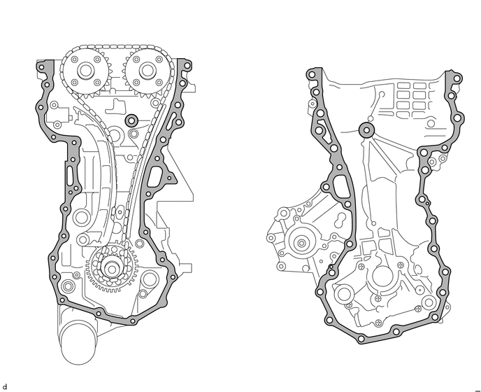
Remove any remaining seal packing material.
Clean the contact surfaces of the timing chain cover sub-assembly, camshaft housing sub-assembly, cylinder head sub-assembly, cylinder block sub-assembly and oil pan sub-assembly, and confirm that no oil, moisture, or other foreign matter is on the surfaces.

|
Surface to be Cleaned | - | - |
Install 3 new O-rings to the oil pan sub-assembly and oil strainer sub-assembly.
Apply seal packing to the timing chain cover sub-assembly as shown in the illustration.
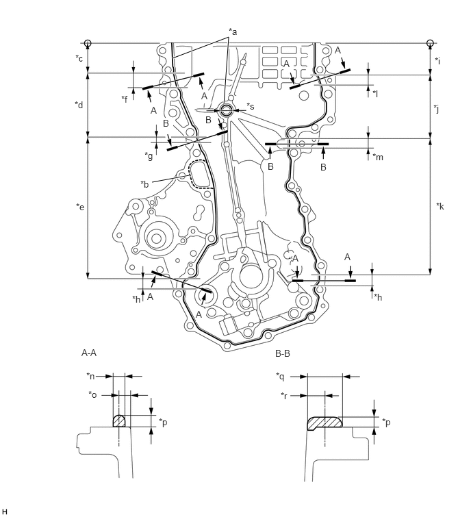
| *a | Toyota Genuine Seal Packing Black, Three Bond 1207B or equivalent | *b | Toyota Genuine Seal Packing 1282B, Three Bond 1282B or equivalent |
| *c | 46.4 mm (1.827 in.) | *d | 104.1 mm (4.098 in.) |
| *e | 229.6 mm (9.039 in.) | *f | 21.1 mm (0.831 in.) |
| *g | 14.0 mm (0.551 in.) | *h | 15.0 mm (0.591 in.) |
| *i | 53.5 mm (2.106 in.) | *j | 102.5 mm (4.035 in.) |
| *k | 221.1 mm (8.705 in.) | *l | 18.5 mm (0.728 in.) |
| *m | 12.0 mm (0.472 in.) | *n | 4.0 to 8.0 mm (0.157 to 0.315 in.) |
| *o | 3.5 mm (0.138 in.) | *p | 3.5 to 4.5 mm (0.138 to 0.177 in.) |
| *q | 13.0 to 15.0 mm (0.512 to 0.591 in.) | *r | 7.0 mm (0.276 in.) |
| *s | 19.5 mm (0.768 in.) | - | - |
- NOTICE:
- ·
If there is oil on the contact surfaces, wipe them with oil-free cloth before applying seal packing.
·Install the timing chain cover sub-assembly within 3 minutes and tighten the bolts within 10 minutes of applying seal packing.
·Do not start the engine for at least 2 hours after installation.
- HINT:
-
Areas A - A and B - B are the joints between the cylinder block sub-assembly and oil pan sub-assembly, the cylinder block sub-assembly and cylinder head sub-assembly, and the cylinder head sub-assembly and camshaft housing sub-assembly.
- Application Specification:
Area Seal Packing Diameter Seal packing Continuous Line Area
Except A - A and B - B3.5 to 4.5 mm (0.138 to 0.177 in.) Toyota Genuine Seal Packing Black, Three Bond 1207B or equivalent Dashed Line Area 2.0 to 3.0 mm (0.0787 to 0.118 in.) Toyota Genuine Seal Packing 1282B, Three Bond 1282B or equivalent
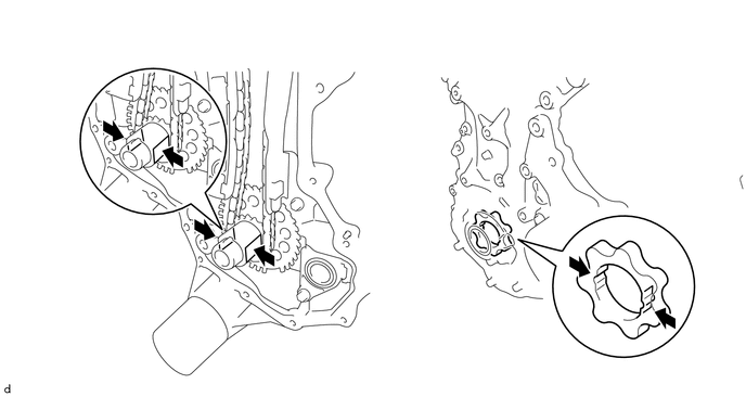
Align the oil pump drive rotor spline and crankshaft as shown in the illustration and install the timing chain cover sub-assembly to the crankshaft.
Apply adhesive to the threads of the bolt (E).
- Adhesive:
Toyota Genuine Adhesive 1324, Three Bond 1324 or equivalent
- HINT:
-
Apply adhesive to the bolt (E) more than 7.0 mm (0.276 in.) from the bolt tip.
Temporarily install the timing chain cover sub-assembly with the 27 bolts and a new gasket.
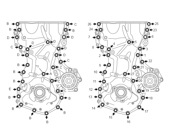
| *1 | Gasket | - | - |
- Bolt Length:
Item Length Bolt (A) 35 mm (1.378 in.) Bolt (B), (E) 25 mm (0.984 in.) Bolt (C) 40 mm (1.575 in.) Bolt (D) 48 mm (1.890 in.)
Fully tighten the timing chain cover assembly with the 27 bolts in the order shown in the illustration.
- Torque:
- Bolt (A) : 10 N*m (102 kgf*cm, 7 ft.*lbf)
- Bolt (B), (C), (E) : 24 N*m (245 kgf*cm, 18 ft.*lbf)
- Bolt (D) : 60.5 N*m (617 kgf*cm, 45 ft.*lbf)
16326
2.INSTALL NO. 2 WATER INLET HOUSING GASKET
16031
3.INSTALL WATER INLET SUB-ASSEMBLY WITH THERMOSTAT
16572D
4.CONNECT NO. 2 RADIATOR HOSE
16281
5.CONNECT NO. 4 WATER BY-PASS HOSE
11302A
6.INSTALL TIMING CHAIN COVER OIL SEAL
13471
7.INSTALL CRANKSHAFT PULLEY
11301K
8.INSTALL CRANK POSITION SENSOR
16620
9.INSTALL V-RIBBED BELT TENSIONER ASSEMBLY
16603
10.INSTALL NO. 1 IDLER PULLY SUB-ASSEMBLY (w/ Air Conditioning System)
11159H
11.INSTALL CAMSHAFT BEARING CAP OIL HOLE GASKET
Install the 2 new camshaft bearing cap oil hole gaskets to the camshaft bearing cap.
- NOTICE:
-
Check that no camshaft bearing cap oil hole gaskets are stuck to the cylinder head cover sub-assembly.
- HINT:
-
The camshaft bearing cap oil hole gaskets can be installed with either side facing upward.
11213
12.INSTALL CYLINDER HEAD COVER GASKET
Install a new cylinder head cover gasket to the cylinder head cover sub-assembly.
- NOTICE:
-
Remove any oil from the contact surfaces.
11201
13.INSTALL CYLINDER HEAD COVER SUB-ASSEMBLY
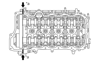
| *a | Seal Diameter 2.0 mm (0.0787 in.) |
Apply seal packing as shown the illustration.
- Seal packing:
Toyota Genuine Seal Packing Black, Three Bond 1207B or equivalent
- Seal diameter:
2.0 mm (0.0787 in.)
- NOTICE:
- ·
Remove any oil from the contact surfaces.
·Install the cylinder head cover sub-assembly within 3 minutes and tighten the bolts within 15 minutes of applying seal packing.
·Do not start the engine for at least 2 hours after the installation.
Temporarily install the cylinder head cover sub-assembly with 2 new seal washers, 2 plate washers and the 17 bolts.
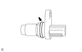
Apply a light coat of engine oil to the 2 O-rings of the 2 cam position sensors.
Temporarily install the 2 cam position sensors with the 2 bolts.
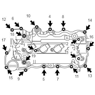
| *1 | Seal Washer and Plate Washer |
| *2 | Camshaft Position Sensor |
Install the 19 bolts in the order shown in the illustration.
- Torque:
- 12 N*m (122 kgf*cm, 9 ft.*lbf)
Connect the 5 harness clamps of the engine wire.
Connect the oxygen sensor connector and 2 camshaft oil control valve assembly connectors.
77754
14.CONNECT NO. 1 CHARCOAL CANISTER OUTLET HOSE (for RHD)
12261
15.CONNECT VENTILATION HOSE
12262
16.CONNECT NO. 2 VENTILATION HOSE
19500
17.INSTALL IGNITION COIL ASSEMBLY
16571C
18.INSTALL NO. 1 RADIATOR HOSE
27020
19.INSTALL GENERATOR ASSEMBLY
20.CONNECT ENGINE WIRE
Connect the engine wire to the timing chain cover sub-assembly with the 2 bolts.
- Torque:
- 8.0 N*m (82 kgf*cm, 71 in.*lbf)
21.CONNECT EARTH CABLE
Connect the earth cable with the bolt.
- Torque:
- 8.0 N*m (82 kgf*cm, 71 in.*lbf)
17700
22.INSTALL AIR CLEANER ASSEMBLY
17750A
23.INSTALL AIR CLEANER INLET ASSEMBLY
24.ADD ENGINE OIL
25.ADD ENGINE COOLANT
26. CHECK ENGINE OIL LEVEL
27.INSPECT FOR ENGINE OIL LEAK
28.INSPECT FOR COOLANT LEAK
51441
29.INSTALL NO. 1 ENGINE UNDER COVER
30.CONNECT CABLE TO NEGATIVE BATTERY TERMINAL
- Torque:
- 6.4 N*m (65 kgf*cm, 57 in.*lbf)