1NR-VE ENGINE CONTROL SFI SYSTEM P0134 Oxygen Sensor (Front) Feedback Malfunction
DESCRIPTION
Refer to P0132.
Click hereEngine / Hybrid System>1NR-VE ENGINE CONTROL>SFI SYSTEM>P0132
- HINT:
-
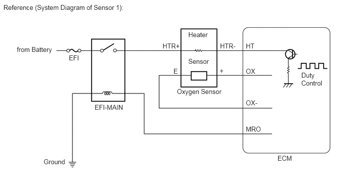
The ECM uses a pulse-width modulated control circuit to adjust current through the heater. The oxygen sensor heater circuit uses a relay on the HTR+ side of the circuit.
| DTC No. | Detection Item | DTC Detection Condition | Trouble Area | MIL | Memory |
|---|---|---|---|---|---|
| P0134 | Oxygen Sensor (Front) Feedback Malfunction | After the engine is warmed up, the oxygen sensor does not indicate a rich condition (output voltage is higher than 0.45 V) even once when conditions (a), (b), (c), (d) and (e) continue for 65 seconds (1 trip detection logic):
(a) Engine speed: 1400 rpm or more. (b) Vehicle speed: 40 km/h (25 mph) or more. (c) The throttle valve is not fully closed. (d) 180 seconds or more have elapsed after starting the engine. (e) The ECT is higher than 40°C (104°F). |
·
Open or short in oxygen sensor circuit ·
Oxygen sensor ·
Ventilation valve and hose ·
Intake system ·
Fuel pressure ·
Fuel injector assembly ·
Gas leakage in exhaust system ·
No. 1 integration relay ·
ECM |
Comes on | DTC stored |
- HINT:
-
Confirm the oxygen sensor voltage. Enter the following menus: Powertrain / EFI / Data List / O2S B1S1.
-
If the voltage is below 0.1 V, the sensor circuit may be open or shorted.
WIRING DIAGRAM
Refer to DTC P0132.
Click hereEngine / Hybrid System>1NR-VE ENGINE CONTROL>SFI SYSTEM>P0132
CONFIRMATION DRIVING PATTERN
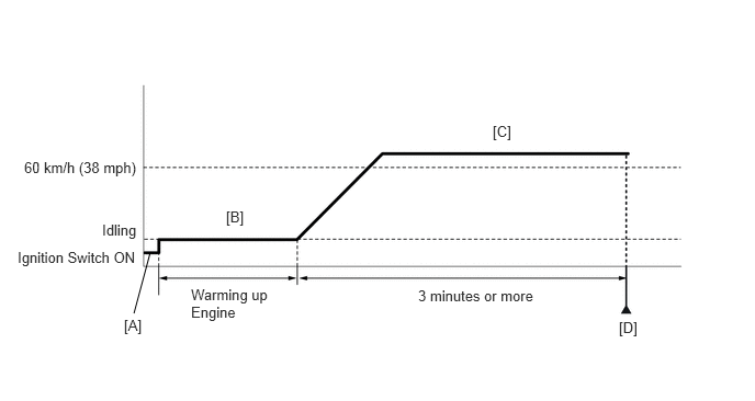
Connect the GTS to the DLC3.
Turn the ignition switch to ON and turn the GTS on.
Clear the DTCs (even if no DTCs are stored, perform the clear DTC operation).
Turn the ignition switch off and wait for at least 30 seconds.
Turn the ignition switch to ON and turn the GTS on [A].
Start the engine and warm it up [B].
Drive the vehicle at 60 km/h (38 mph) or more for 3 minutes or more [C].
Enter the following menus: Powertrain / EFI / Trouble Codes [D].
Read the pending DTCs.
- HINT:
- ·
If a pending DTC is output, the system is malfunctioning.
·If a pending DTC is not output, the system is normal.
CAUTION / NOTICE / HINT
- HINT:
-
Read freeze frame data using the GTS. Freeze frame data records the engine conditions when a malfunction is detected. When troubleshooting, freeze frame data can help determine if the vehicle was moving or stationary, if the engine was warmed up or not, if the air-fuel ratio was lean or rich, and other data from the time the malfunction occurred.
PROCEDURE
Connect the GTS to the DLC3.
Turn the ignition switch to ON.
Turn the GTS on.
Enter the following menus: Powertrain / EFI / Trouble Codes.
Read the DTCs.
- Result:
Result Proceed to DTC P0134 is output A DTC P0134 and other DTCs are output B
A
B
Connect the GTS to the DLC3.
Turn the ignition switch to ON.
Turn the GTS on.
Enter the following menus: Powertrain / EFI / Data List / O2S B1S1.
Allow the engine to idle until the ECT reaches 40°C (104°F).
Quickly depress the accelerator pedal 3 times until the engine speed reaches 4000 rpm. Then, read the oxygen sensor voltage.
- Standard voltage:
The oxygen sensor voltage is 0.45 V or higher at least once.
- Result:
Proceed to OK NG
OK
NG
- HINT:
-
Refer to Confirmation Driving Pattern.
- Result:
Proceed to NEXT
NEXT
Connect the GTS to the DLC3.
Turn the ignition switch to ON.
Turn the GTS on.
Start the engine and allow it to idle for 15 seconds or more.
Enter the following menus: Powertrain / EFI / Trouble Codes.
Read the DTCs.
- Result:
Result Proceed to No DTC is output A DTC P0134 is output B
A
B
Confirm if the vehicle has run out of fuel.
- Result:
Result Proceed to The vehicle has run out of fuel A The vehicle has not run out of fuel B
A
B
Check the PCV hose connections.
Click hereEngine / Hybrid System>1NR-VE EMISSION CONTROL>EMISSION CONTROL SYSTEM>ON-VEHICLE INSPECTION
- OK:
PCV hose is connected correctly and is not damaged.
- Result:
Proceed to OK NG
OK
NG
Inspect the oxygen sensor.
Click hereEngine / Hybrid System>1NR-VE ENGINE CONTROL>HEATED OXYGEN SENSOR>INSPECTION
- Result:
Proceed to OK NG
OK
NG
Inspect the No. 1 integration relay (EFI-MAIN).
Click hereEngine / Hybrid System>1NR-VE ENGINE CONTROL>INTEGRATION RELAY>INSPECTION
- Result:
Proceed to OK NG
OK
NG
Disconnect the oxygen sensor connector.
Disconnect the ECM connectors.
Measure the resistance according to the value(s) in the table below.
- Standard Resistance:
Tester Connection Condition Specified Condition C22-1 (HTR-) - C50-8 (OXH1) Always Below 1 Ω C22-3 (+) - C50-30 (OX) Always Below 1 Ω C22-4 (E) - C50-51 (OX-) Always Below 1 Ω C22-1 (HTR-) or C50-8 (OXH1) - Body ground Always 10 kΩ or higher C22-3 (+) or C50-30 (OX) - Body ground Always 10 kΩ or higher
- Result:
Proceed to OK NG
OK
NG
Check the intake system for vacuum leakage.
Click hereEngine / Hybrid System>1NR-VE INTAKE / EXHAUST>INTAKE SYSTEM>ON-VEHICLE INSPECTION
- OK:
No leakage from intake system.
- Result:
Proceed to OK NG
OK
NG
Check the fuel pressure.
Click hereEngine / Hybrid System>1NR-VE FUEL>FUEL SYSTEM>ON-VEHICLE INSPECTION
- Result:
Proceed to OK NG
OK
NG
Check the fuel injector assembly injection [whether fuel volume is high or low, and whether injection pattern is poor].
Click hereEngine / Hybrid System>1NR-VE FUEL>FUEL INJECTOR>INSPECTION
- Result:
Proceed to OK NG
OK
NG
Check for exhaust gas leakage.
- OK:
No gas leakage.
- Result:
Proceed to OK NG
OK
NG