HEATING / AIR CONDITIONING COMPRESSOR REMOVAL
CAUTION / NOTICE / HINT
The necessary procedures (adjustment, calibration, initialization, or registration) that must be performed after parts are removed, installed, or replaced during the compressor with motor assembly removal/installation are shown below.
| Replaced Part or Performed Procedure | Necessary Procedure | Effect/Inoperative Function when Necessary Procedure not Performed | Link |
|---|---|---|---|
|
*1: When performing learning using the GTS. Click here( |
|||
| Disconnect cable from negative auxiliary battery terminal | Perform steering sensor zero point calibration | Lane departure alert system (w/ Steering Control) | ( ) |
| Toyota parking assist-sensor system*1 | |||
| Parking support brake system*1 | |||
| Simple intelligent parking assist system*1 | |||
| Pre-collision system | |||
| Memorize steering angle neutral point | Panoramic view monitor system | ()
|
|
| Initialize back door lock | Power door lock control system | ()
|
|
- CAUTION:
- ·
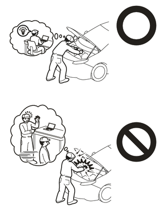
This vehicle has contains high voltage circuits standardized with orange colored wiring and connectors, so follow the instructions in this manual to perform the procedures correctly.
for M20A-FXS
Click hereEngine / Hybrid System>M20A-FXS (HYBRID / BATTERY CONTROL)>HYBRID CONTROL SYSTEM>PRECAUTION
for 2ZR-FXE with NICKEL METAL HYDRIDE BATTERY
for 2ZR-FXE with LITHIUM-ION BATTERY
·If the correct procedures are not followed according to the instructions in this manual, there is a danger of electric shock from the high voltage circuits.
·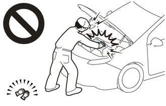
Be sure to wear insulating gloves when working on high voltage wiring or components.
·If work is performed without wearing insulating gloves, there is a danger of electric shock.
- NOTICE:
- ·
After the power switch is turned off, the radio and display receiver assembly records various types of memory and settings. As a result, after turning the power switch off, make sure to wait at least 120 seconds before disconnecting the cable from the negative (-) auxiliary battery terminal (for Audio and Visual System).
·After the power switch is turned off, the radio and display receiver assembly records various types of memory and settings. As a result, after turning the power switch off, make sure to wait at least 120 seconds before disconnecting the cable from the negative (-) auxiliary battery terminal (for Navigation System (for Radio and Display Type)).
PROCEDURE

 1.RECOVER REFRIGERANT FROM REFRIGERATION SYSTEM
for HFC-134a(R134a):
Click hereVehicle Interior>HEATING / AIR CONDITIONING>REFRIGERANT (for HFC-134a(R134a))>REPLACEMENT
for HFO-1234yf(R1234yf):
Click hereVehicle Interior>HEATING / AIR CONDITIONING>REFRIGERANT(for HFO-1234yf(R1234yf))>REPLACEMENT
G3834
2.REMOVE SERVICE PLUG GRIP
for 2ZR-FXE:
Click hereEngine / Hybrid System>2ZR-FXE (HYBRID / BATTERY CONTROL)>SERVICE PLUG GRIP>REMOVAL
for M20A-FXS:
Click hereEngine / Hybrid System>M20A-FXS (HYBRID / BATTERY CONTROL)>SERVICE PLUG GRIP>REMOVAL
82121
3.DISCONNECT ENGINE WIRE
for 2ZR-FXE:
Click hereEngine / Hybrid System>2ZR-FXE (HYBRID / BATTERY CONTROL)>FRAME WIRE>REMOVAL
for M20A-FXS:
Click hereEngine / Hybrid System>M20A-FXS (HYBRID / BATTERY CONTROL)>FRAME WIRE>REMOVAL
4.REMOVE CONNECTOR COVER ASSEMBLY
for 2ZR-FXE:
Click hereEngine / Hybrid System>M20A-FXS (HYBRID / BATTERY CONTROL)>INVERTER WITH CONVERTER>REMOVAL
for M20A-FXS:
Click hereEngine / Hybrid System>2ZR-FXE (HYBRID / BATTERY CONTROL)>INVERTER WITH CONVERTER>REMOVAL
5.CHECK TERMINAL VOLTAGE
for 2ZR-FXE:
Click hereEngine / Hybrid System>2ZR-FXE (HYBRID / BATTERY CONTROL)>INVERTER WITH CONVERTER>REMOVAL
for M20A-FXS:
Click hereEngine / Hybrid System>M20A-FXS (HYBRID / BATTERY CONTROL)>INVERTER WITH CONVERTER>REMOVAL
6.INSTALL CONNECTOR COVER ASSEMBLY
for 2ZR-FXE with NICKEL METAL HYDRIDE BATTERY
for 2ZR-FXE with LITHIUM-ION BATTERY
for M20A-FXS:
Click hereEngine / Hybrid System>M20A-FXS (HYBRID / BATTERY CONTROL)>HV BATTERY>REMOVAL
82121
7.CONNECT ENGINE WIRE
for 2ZR-FXE:
Click hereEngine / Hybrid System>2ZR-FXE (HYBRID / BATTERY CONTROL)>FRAME WIRE>INSTALLATION
for M20A-FXS:
Click hereEngine / Hybrid System>M20A-FXS (HYBRID / BATTERY CONTROL)>FRAME WIRE>INSTALLATION
51441
8.REMOVE NO. 1 ENGINE UNDER COVER ASSEMBLY
for 2ZR-FXE:
Click hereEngine / Hybrid System>2ZR-FXE (ENGINE MECHANICAL)>ENGINE ASSEMBLY>REMOVAL
for M20A-FXS:
Click hereEngine / Hybrid System>M20A-FXS (ENGINE MECHANICAL)>ENGINE ASSEMBLY>REMOVAL
88703
9.DISCONNECT DISCHARGE HOSE SUB-ASSEMBLY
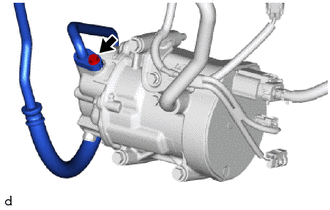
Remove the bolt to disconnect the discharge hose sub-assembly from the compressor with motor assembly.
Remove the O-ring from the refrigerant discharge hose sub-assembly.
- NOTICE:
-
Wrap protective tape around the connecting portions of the disconnected refrigerant discharge hose sub-assembly and compressor with motor assembly to prevent contamination by foreign matter or water droplets.
88704
10.DISCONNECT SUCTION HOSE SUB-ASSEMBLY
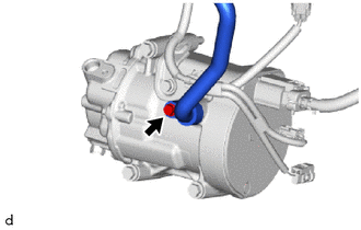
Remove the bolt to disconnect the suction hose sub-assembly from the compressor with motor assembly.
Remove the O-ring from the suction hose sub-assembly.
- NOTICE:
-
Wrap protective tape around the connecting portions of the disconnected suction hose sub-assembly and the compressor with motor assembly to prevent contamination by foreign matter or water droplets.
88370
11.REMOVE COMPRESSOR WITH MOTOR ASSEMBLY (for 2ZR-FXE)
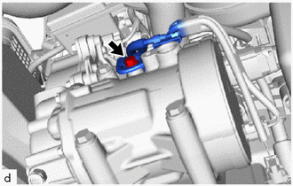
Remove the bolt and disconnect the bracket.
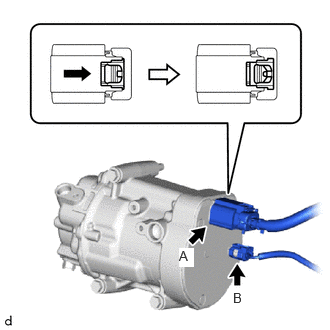
Slide the green-colored lock of the connector A as shown in the illustration to release it and disconnect the connector.
- CAUTION:
-
Make sure to wear insulating gloves.
- NOTICE:
-
Insulate the disconnected terminals and connector with insulating tape.
Disconnect the connector B.
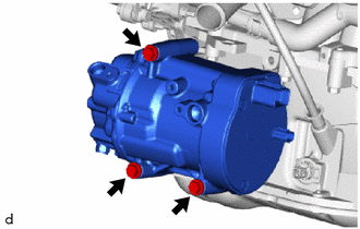
Remove the 3 bolts and compressor with motor assembly.
88370
12.REMOVE COMPRESSOR WITH MOTOR ASSEMBLY (for M20A-FXS)
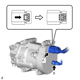
Slide the green-colored lock of the connector A as shown in the illustration to release it and disconnect the connector.
- CAUTION:
-
Make sure to wear insulating gloves.
- NOTICE:
-
Insulate the disconnected terminals and connector with insulating tape.
Disconnect the connector B.
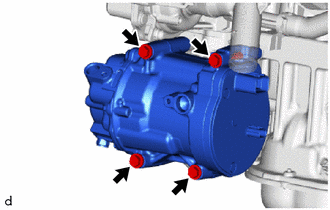
Remove the 4 bolts and compressor with motor assembly.