M20A-FXS COOLING RADIATOR INSTALLATION
PROCEDURE

 1.INSTALL RADIATOR DRAIN COCK PLUG
Install the 2 O-rings to the 2 radiator drain cock plugs.
- NOTICE:
-
Replace the O-ring if it is damaged.
Install the 2 radiator drain cock plugs.
16533C
2.INSTALL LOWER RADIATOR SUPPORT
Install the 2 lower radiator supports to the radiator assembly.
16523A
3.INSTALL RADIATOR SUPPORT CUSHION
Install the 2 radiator support cushions to the radiator assembly.
16400
4.INSTALL RADIATOR ASSEMBLY
Engage the 2 guides.
Engage the 2 claws to install the fan shroud assembly to the radiator assembly.
- NOTICE:
-
Do not damage the radiator assembly when installing the fan shroud assembly.
Install the radiator assembly together with the fan shroud assembly to the vehicle.
88460
5.INSTALL COOLER CONDENSER ASSEMBLY
88707
6.CONNECT SUCTION PIPE SUB-ASSEMBLY
88703
7.CONNECT DISCHARGE HOSE SUB-ASSEMBLY
16595B
8.INSTALL NO. 1 RADIATOR AIR GUIDE LH
16593B
9.INSTALL NO. 1 RADIATOR AIR GUIDE RH
52131A
10.INSTALL FRONT BUMPER REINFORCEMENT
52611
11.INSTALL FRONT BUMPER ENERGY ABSORBER
G922F
12.INSTALL NO. 1 HYBRID WATER PUMP OUTLET HOSE
Engage the clamp to install the No. 1 hybrid water pump outlet hose to the fan shroud.
G922E
13.INSTALL HYBRID WATER PUMP INLET HOSE
Engage the 3 clamps to install the hybrid water pump inlet hose to the fan shroud.
14.INSTALL NO. 1 INVERTER COOLING OUTLET HOSE
Engage the 2 clamps to install the No. 1 inverter cooling outlet hose to the fan shroud.
Engage the claw.
G922AA
15.CONNECT NO. 1 INVERTER COOLING INLET HOSE
Connect the No. 1 inverter cooling inlet hose to the radiator assembly and slide the clip to secure it.
G922H
16.CONNECT HYBRID RADIATOR INLET HOSE
Connect the hybrid radiator inlet hose to the radiator assembly and slide the clip to secure it.
Engage the clamp.
16572D
17.CONNECT NO. 2 RADIATOR HOSE
Connect the No. 2 radiator hose to the radiator assembly and slide the clip to secure it.
Engage the clamp.
16571C
18.CONNECT NO. 1 RADIATOR HOSE
Connect the No. 1 radiator hose to the radiator assembly and slide the clip to secure it.
Engage the clamp.
16264D
19.CONNECT NO. 2 WATER BY-PASS HOSE
Connect the No. 2 water by-pass hose to the radiator assembly and slide the clip to secure it.
Engage the 3 clamps to the fan shroud.
16261
20.CONNECT WATER BY-PASS HOSE
Connect the water by-pass hose to the radiator assembly and slide the clip to secure it.
16594
21.INSTALL NO. 2 RADIATOR AIR GUIDE
Engage the 3 guides and 2 claws to install the No. 2 radiator air guide to the radiator assembly.
53205
22.INSTALL UPPER RADIATOR SUPPORT SUB-ASSEMBLY
Install the upper radiator support sub-assembly together with hood lock support sub-assembly to the vehicle with the 5 bolts.
- Torque:
- 12.5 N*m (127 kgf*cm, 9 ft.*lbf)
Engage the 3 clamps to connect the wire harness to the fan shroud.
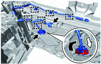
Connect the wire harness connector to the cooling fan motor and lock with the lever.
Connect the wire harness connector to the cooling fan wire.
Engage the 7 clamps to connect the wire harness to the fan shroud and upper radiator support sub-assembly.
Engage the 3 clamps to connect the wire harness to the horn and hood lock support assembly.
Engage the clamp to connect the hood control cable sub-assembly to the upper radiator support sub-assembly.
17751
23.INSTALL NO. 1 AIR CLEANER INLET
Install the No. 1 air cleaner inlet to the upper radiator support sub-assembly and air cleaner case sub-assembly with the 4 bolts.
- Torque:
- 4.0 N*m (41 kgf*cm, 35 in.*lbf)
53510
24.INSTALL HOOD LOCK ASSEMBLY
w/ Engine Hood Courtesy Switch :
Click hereVehicle Interior>THEFT DETERRENT / KEYLESS ENTRY>ENGINE HOOD COURTESY SWITCH>INSTALLATION
w/o Engine Hood Courtesy Switch :
Click hereVehicle Exterior>DOOR / HATCH>HOOD LOCK CONTROL CABLE ASSEMBLY>INSTALLATION
53579
25.INSTALL HOOD LOCK NUT CAP
16561C
26.INSTALL NO. 1 RADIATOR TO SUPPORT SEAL
53117C
27.INSTALL NO. 1 RADIATOR GRILLE RETAINER
28.INSTALL FRONT BUMPER UPPER REINFORCEMENT SUB-ASSEMBLY
Install the front bumper upper reinforcement sub-assembly to the vehicle with the 4 bolts.
- Torque:
- 12 N*m (122 kgf*cm, 9 ft.*lbf)
G9040
29.INSTALL INVERTER WATER PUMP WITH MOTOR ASSEMBLY
30.INSTALL HEADLIGHT ASSEMBLY LH
for Triple Beam Headlight:
Click hereVehicle Exterior>LIGHTING (EXT)>HEADLIGHT ASSEMBLY (for Triple Beam Headlight)>INSTALLATION
for Single Beam Headlight:
Click hereVehicle Exterior>LIGHTING (EXT)>HEADLIGHT ASSEMBLY (for Single Beam Headlight)>INSTALLATION
31.INSTALL HEADLIGHT ASSEMBLY RH
- HINT:
-
Use the same procedure as for the LH side.
32.ADD ENGINE COOLANT (for Engine)
33. CHARGE AIR CONDITIONING SYSTEM WITH REFRIGERANT
34.INSPECT FOR COOLANT LEAK (for Engine)
51410
35.INSTALL NO. 1 ENGINE UNDER COVER ASSEMBLY
36.WARM UP COMPRESSOR
37.INSPECT FOR REFRIGERANT LEAK