8NR-FTS ENGINE MECHANICAL CAMSHAFT INSTALLATION
CAUTION / NOTICE / HINT
- HINT:
-
Perform "Inspection After Repair" after replacing the camshaft, No. 2 camshaft, camshaft timing gear assembly or camshaft timing exhaust gear assembly.
-
Click hereEngine / Hybrid System>8NR-FTS (ENGINE CONTROL)>SFI SYSTEM>INITIALIZATION
PROCEDURE

 13801
1.SET NO. 1 VALVE ROCKER ARM SUB-ASSEMBLY
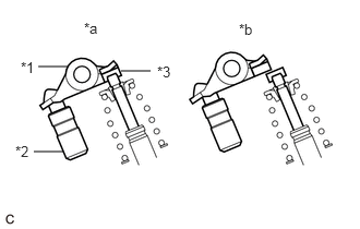
| *1 | No. 1 Valve Rocker Arm Sub-assembly |
| *2 | Valve Lash Adjuster Assembly |
| *3 | Valve Stem Cap |
| *a | Correct |
| *b | Incorrect |
Make sure that the No. 1 valve rocker arm sub-assemblies are installed as shown in the illustration.
11103
2.INSTALL CAMSHAFT HOUSING SUB-ASSEMBLY
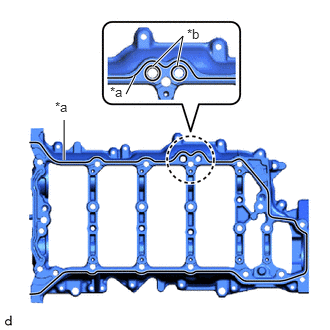
| *a | Seal Packing |
| *b | Oil Line |
Apply seal packing in a continuous line as shown in the illustration.
- Seal Packing:
Toyota Genuine Seal Packing Black, Three Bond 1207B or equivalent
- Seal Packing Diameter:
3.5 to 4.0 mm (0.138 to 0.157 in.)
- NOTICE:
- ·
Prevent Seal Packing from entering the oil passages.
·Remove any oil from the contact surface.
·Install the camshaft housing sub-assembly within 3 minutes and tighten the bolts within 15 minutes of applying seal packing.
·Do not start the engine for at least 2 hours after installation.
Set the camshaft housing sub-assembly to the cylinder head sub-assembly.
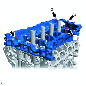
Tighten the 4 bolts in the order shown in the illustration.
- Torque:
- 28 N*m (286 kgf*cm, 21 ft.*lbf)
15678A
3.INSTALL OIL CONTROL VALVE FILTER
13512
4.INSTALL NO. 2 CAMSHAFT
Clean the No. 2 camshaft journals.
Apply a light coat of engine oil to the No. 2 camshaft journals and camshaft housing sub-assembly.
Install the No. 2 camshaft to the camshaft housing sub-assembly.
13511
5.INSTALL CAMSHAFT
Clean the camshaft journals.
Apply a light coat of engine oil to the camshaft journals and camshaft housing sub-assembly.
Install the camshaft to the camshaft housing sub-assembly.
6.INSTALL CAMSHAFT BEARING CAP
16671
7.INSTALL WATER VALVE
13070A
8.INSTALL CAMSHAFT TIMING EXHAUST GEAR ASSEMBLY
13050
9.INSTALL CAMSHAFT TIMING GEAR ASSEMBLY
10.SET NO. 1 CYLINDER TO TDC/COMPRESSION
13506
11.INSTALL CHAIN SUB-ASSEMBLY
- HINT:
- ·
Be sure to install the chain sub-assembly with the mark plates facing away from the engine assembly.
·Pass the chain sub-assembly through the timing chain guide.
Temporarily install the crankshaft pulley set bolt.
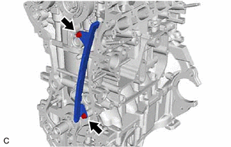
Install the timing chain guide with the 2 bolts to the cylinder head sub-assembly and cylinder block sub-assembly.
- Torque:
- 10 N*m (102 kgf*cm, 7 ft.*lbf)
Align the mark plates (gold) with the timing marks as shown in the illustration and install the chain sub-assembly.
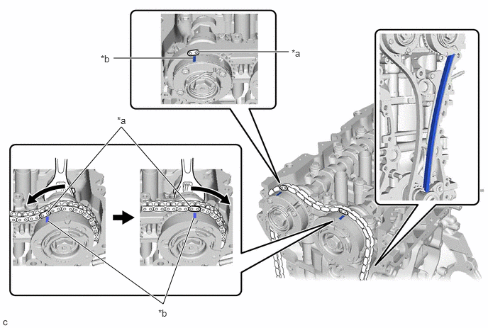
| *a | Mark Plate (Gold) | *b | Timing Mark |
- HINT:
-
Do not pass the chain sub-assembly around the sprocket of the camshaft timing gear assembly. Only place it on the sprocket.
Hold the hexagonal portion of the camshaft with a wrench and turn the camshaft timing gear assembly clockwise.
- HINT:
-
To tension the chain sub-assembly, slowly turn the camshaft timing gear assembly clockwise to prevent the chain sub-assembly from being misaligned.
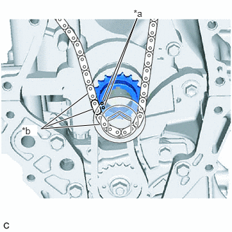
| *a | Timing Mark |
| *b | Mark Plate (Gold) |
Align the mark plate (gold) and timing mark and install the chain sub-assembly to the crankshaft timing sprocket.
- NOTICE:
-
The mark for the crankshaft spans 3 outer links. Use the center mark plate for the alignment.
Remove the crankshaft pulley set bolt from the crankshaft.
13559
12.INSTALL CHAIN TENSIONER SLIPPER
13540
13.INSTALL NO. 1 CHAIN TENSIONER ASSEMBLY
14.CHECK NO. 1 CYLINDER TDC/COMPRESSION
16322
15.INSTALL WATER INLET PIPE
11302A
16.INSTALL TIMING CHAIN COVER OIL SEAL
11310
17.INSTALL TIMING CHAIN COVER ASSEMBLY
13470
18.INSTALL CRANKSHAFT PULLEY ASSEMBLY
11191A
19.INSTALL SPARK PLUG TUBE GASKET
11213
20.INSTALL CYLINDER HEAD COVER GASKET
21.ADD ENGINE OIL
11201
22.INSTALL CYLINDER HEAD COVER SUB-ASSEMBLY
15370
23.INSTALL CAMSHAFT TIMING OIL CONTROL SOLENOID ASSEMBLY (for Exhaust Side)
15370
24.INSTALL CAMSHAFT TIMING OIL CONTROL SOLENOID ASSEMBLY (for Intake Side)
29300
25.INSTALL VACUUM PUMP ASSEMBLY
11452
26.INSTALL ENGINE OIL LEVEL DIPSTICK GUIDE
16206
27.INSTALL WATER BY-PASS PIPE SUB-ASSEMBLY
23818
28.INSTALL FUEL VAPOR FEED PIPE
19500D
29.INSTALL NO. 1 IGNITION COIL
23100X
30.INSTALL FUEL PUMP ASSEMBLY
23250
31.INSTALL FUEL INJECTOR ASSEMBLY
17201
32.INSTALL TURBOCHARGER SUB-ASSEMBLY
33.INSTALL ENGINE HANGERS
34.REMOVE ENGINE ASSEMBLY FROM ENGINE STAND