2TR-FE ENGINE MECHANICAL ENGINE ASSEMBLY REMOVAL
PROCEDURE

 1.DISCHARGE FUEL SYSTEM PRESSURE
2.DISCONNECT CABLE FROM NEGATIVE BATTERY TERMINAL
3.DRAIN ENGINE COOLANT
4.DRAIN ENGINE OIL
16400
5.REMOVE RADIATOR ASSEMBLY
16572D
6.REMOVE NO. 2 RADIATOR HOSE
17410
7.REMOVE FRONT EXHAUST PIPE ASSEMBLY
17861
8.REMOVE INTAKE AIR CONNECTOR
22030
9.REMOVE THROTTLE WITH MOTOR BODY ASSEMBLY
44360
10.SEPARATE VANE PUMP OIL RESERVOIR ASSEMBLY
Remove the 4 bolts, and separate the vane pump oil reservoir.
44310
11.SEPARATE VANE PUMP ASSEMBLY
27020
12.REMOVE GENERATOR ASSEMBLY (for 80A Type)
27020
13.REMOVE GENERATOR ASSEMBLY (for 100A Type)
88320
14.SEPARATE COMPRESSOR AND MAGNETIC CLUTCH
Disconnect the connector.
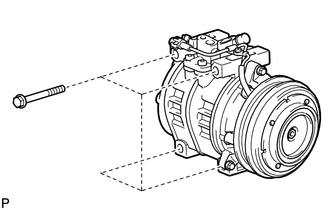
Remove the 4 bolts, and then separate the compressor from the engine.
Support the compressor securely.
44776
15.DISCONNECT BRAKE BOOSTER HOSE
Disconnect the vacuum hose from the intake manifold.
87245A
16.DISCONNECT HEATER WATER HOSE INLET A
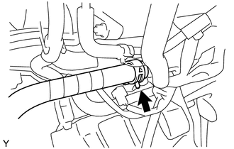
Disconnect the heater water hose inlet A.
87246A
17.DISCONNECT HEATER WATER HOSE OUTLET E
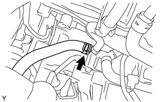
Disconnect the heater water hose outlet E.
23271F
18.DISCONNECT FUEL HOSE
23273C
19.DISCONNECT NO. 2 FUEL HOSE
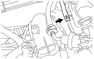
Disconnect the No. 2 fuel hose.
23270
20.REMOVE FUEL PRESSURE PULSATION DAMPER ASSEMBLY
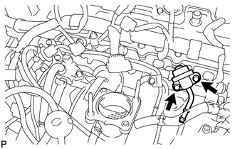
Remove the 2 bolts and fuel pressure pulsation damper.
23807
21.REMOVE FUEL DELIVERY PIPE SUB-ASSEMBLY
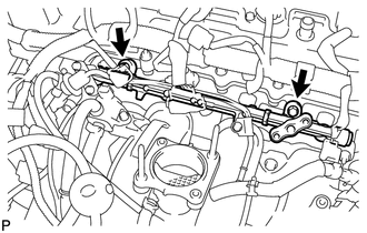
Remove the 2 bolts and fuel delivery pipe with the 4 fuel injectors.
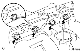
Using screwdriver, pry out the 4 injector spacers from the cylinder head.
Remove the 4 O-rings from the 4 injector spacers.
23250
22.REMOVE FUEL INJECTOR ASSEMBLY
23.REMOVE FUEL HOSE CLAMP
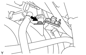
Remove the bolt, and then remove the fuel hose clamp from the intake manifold.
45450
24.SEPARATE STEERING RELAY ROD ASSEMBLY
Remove the 4 cotter pins.
Remove the 4 nuts.
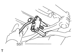
Using SST, separate the tie rod end LH from the steering relay rod.
- SST
- 09628-62011
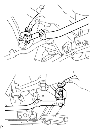
Using SST, separate the steering relay rod from the center arm.
- SST
- 09611-20015
51202
25.REMOVE NO. 2 FRAME CROSSMEMBER SUB-ASSEMBLY
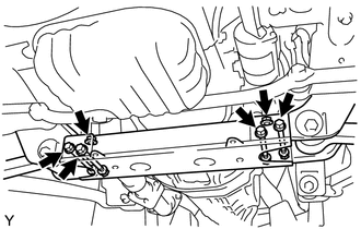
Remove the 4 nuts and 6 bolts, and then remove the No. 2 frame crossmember sub-assembly.
33110
26.REMOVE MANUAL TRANSMISSION ASSEMBLY
27.SET ENGINE STAND
Support the engine.
82121
28.SEPARATE ENGINE WIRE
Separate the connectors and clamps from the engine.
12311
29.REMOVE NO. 1 FRONT ENGINE MOUNTING BRACKET RH
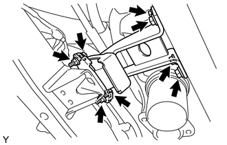
Remove the 6 bolts and 2 nuts, and then remove the No. 1 front engine mounting bracket RH.
30.REMOVE ENGINE ASSEMBLY
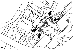
Remove the 2 bolts and 2 nuts, and then separate the No. 1 engine mounting bracket LH.
Remove the engine assembly.
31210
31.REMOVE CLUTCH COVER ASSEMBLY
31250
32.REMOVE CLUTCH DISC ASSEMBLY
13405
33.REMOVE FLYWHEEL SUB-ASSEMBLY
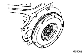
Hold the crankshaft pulley.
Remove the 10 bolts and flywheel.
19500
34.REMOVE IGNITION COIL ASSEMBLY
Remove the 4 bolts, and then remove the 4 ignition coils.
17111
35.REMOVE INTAKE MANIFOLD
Disconnect the ventilation hose.
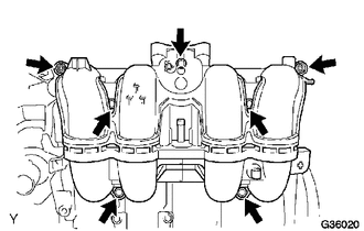
Remove the 2 nuts and 5 bolts, and then remove the intake manifold with the gasket.
36.REMOVE HOSE CLAMP BRACKET
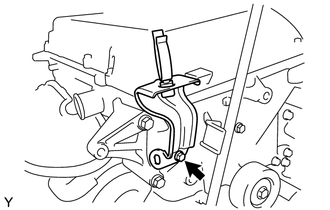
Remove the bolt and hose clamp bracket.
16603
37.REMOVE NO. 1 IDLER PULLEY SUB-ASSEMBLY
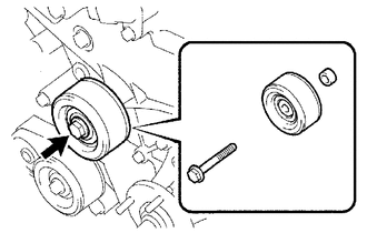
Remove the bolt, No. 1 idler pulley sub-assembly and spacer.
15301
38.REMOVE OIL LEVEL DIPSTICK SUB-ASSEMBLY
11452
39.REMOVE OIL LEVEL DIPSTICK GUIDE
Remove the bolt and the oil level dipstick guide with O-ring.
Remove the O-ring from oil level dipstick guide.
88431
40.REMOVE NO. 1 COMPRESSOR MOUNTING BRACKET
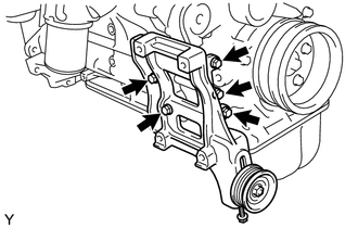
Remove the 5 bolts and compressor mounting bracket.
13471
41.REMOVE CRANKSHAFT PULLEY
Remove the 4 bolts and crankshaft pulley.
16261
42.DISCONNECT WATER BY-PASS HOSE
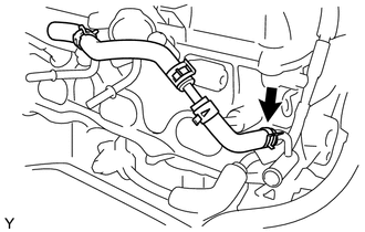
Disconnect the water by-pass hose.
12229
43.REMOVE VENTILATION PIPE
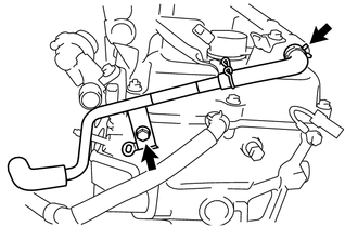
Disconnect the No. 1 ventilation hose.
Remove the bolt and ventilation pipe.
16268
44.REMOVE NO. 1 WATER BY-PASS PIPE
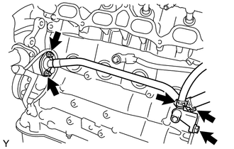
Disconnect the 2 water by-pass hoses.
Remove the bolt and 2 nuts, and then remove the No. 1 water by-pass pipe.
45.REMOVE WIRE HARNESS
Disconnect the wire harness from the knock sensor.
11355
46.REMOVE REAR END PLATE
Remove the 2 bolts and rear end plate.
17167
47.REMOVE NO. 1 EXHAUST MANIFOLD HEAT INSULATOR
17141
48.REMOVE EXHAUST MANIFOLD
16281
49.DISCONNECT NO. 4 WATER BY-PASS HOSE
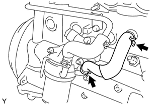
Disconnect the No. 4 water by-pass hose.
16288
50.REMOVE NO. 4 WATER BY-PASS PIPE
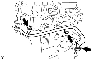
Disconnect the No. 5 water by-pass hose from engine oil cooler.
Remove the 2 bolts and No. 4 water by-pass pipe.
12315
51.REMOVE NO. 1 FRONT ENGINE MOUNTING BRACKET LH
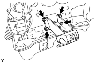
Remove the 4 bolts and No. 1 front engine mounting bracket LH.