2TR-FE ENGINE MECHANICAL ENGINE ASSEMBLY INSTALLATION
PROCEDURE

 12315
1.INSTALL NO. 1 FRONT ENGINE MOUNTING BRACKET LH
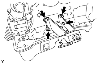
Install the No. 1 front engine mounting bracket LH with the 4 bolts.
- Torque:
51 N*m (520 kgf*cm, 38 ft.*lbf)
16288
2.INSTALL NO. 4 WATER BY-PASS PIPE
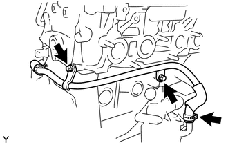
Connect the No. 5 water by-pass hose to the oil cooler.
Install the No. 4 water by-pass pipe with the 2 bolts.
- Torque:
20 N*m (204 kgf*cm, 15 ft.*lbf)
16281
3.INSTALL NO. 4 WATER BY-PASS HOSE
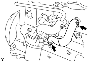
Install the No. 4 water by-pass hose.
17141
4.INSTALL EXHAUST MANIFOLD
17167
5.INSTALL NO. 1 EXHAUST MANIFOLD HEAT INSULATOR
11355
6.INSTALL REAR END PLATE
Install the rear end plate with the 2 bolts.
- Torque:
18 N*m (184 kgf*cm, 13 ft.*lbf)
7.CONNECT WIRE HARNESS
Connect the wire harness to the knock sensor.
16268
8.INSTALL NO. 1 WATER BY-PASS PIPE
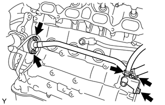
Install the No. 1 water by-pass pipe with the 2 nuts and bolt.
- Torque:
- Nut:
18 N*m (178 kgf*cm, 13 ft.*lbf)
- Bolt:
18 N*m (178 kgf*cm, 13 ft.*lbf)
Connect the 2 water by-pass hoses.
12229
9.INSTALL VENTILATION PIPE
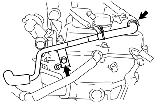
Install the ventilation pipe with the bolt.
- Torque:
18 N*m (184 kgf*cm, 13 ft.*lbf)
Connect the No. 1 ventilation hose.
16261
10.INSTALL WATER BY-PASS HOSE
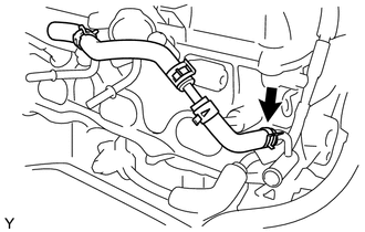
Install the water by-pass hose.
13471
11.INSTALL CRANKSHAFT PULLEY
Install the crankshaft pulley with the 4 bolts.
- Torque:
18 N*m (184 kgf*cm, 13 ft.*lbf)
88431
12.INSTALL NO. 1 COMPRESSOR MOUNTING BRACKET
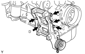
Temporarily tighten bolt E and tighten bolt A to the specified torque.
- Torque:
60 N*m (612 kgf*cm, 44 ft.*lbf)
- NOTICE:
-
Make sure that there is no gap between the bracket and engine.
Tighten bolts B, C, D and E.
- Torque:
- Bolt B, CNut:
25 N*m (250 kgf*cm, 18 ft.*lbf)
- Bolt D, E:
60 N*m (612 kgf*cm, 44 ft.*lbf)
11452
13.INSTALL OIL LEVEL DIPSTICK GUIDE
Apply a light coat of engine oil to a new O-ring.
Install the new O-ring onto the oil level dipstick guide.
Install the oil level dipstick guide with the bolt.
- Torque:
8.0 N*m (82 kgf*cm, 71 in.*lbf)
15301
14.INSTALL OIL LEVEL DIPSTICK SUB-ASSEMBLY
16603
15.INSTALL NO. 1 IDLER PULLEY SUB-ASSEMBLY
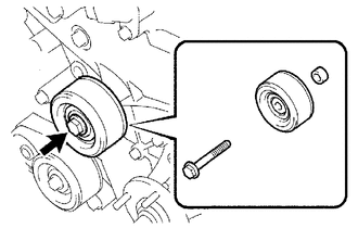
Install the spacer and idler pulley with the bolt.
- Torque:
43 N*m (438 kgf*cm, 32 ft.*lbf)
16.INSTALL HOSE CLAMP BRACKET
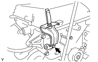
Install the hose clamp bracket with the bolt.
- Torque:
8.5 N*m (87 kgf*cm, 75 in.*lbf)
17111
17.INSTALL INTAKE MANIFOLD
Install a new gasket onto the intake manifold.
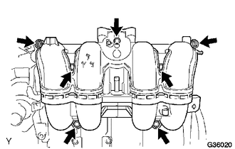
Install the intake manifold with the 2 nuts and 5 bolts.
- Torque:
25 N*m (255 kgf*cm, 18 ft.*lbf)
Connect the ventilation hose.
19500
18.INSTALL IGNITION COIL ASSEMBLY
Install the 4 ignition coils with the 4 bolts.
- Torque:
9.0 N*m (92 kgf*cm, 80 in.*lbf)
13405
19.INSTALL FLYWHEEL SUB-ASSEMBLY
- HINT:
- ·
The mounting bolts are tightened in 2 progressive steps.
·If any of the mounting bolts is broken or deformed, replace it.
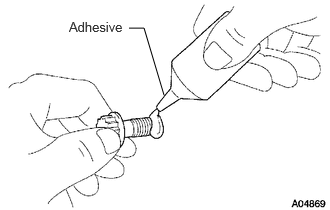
Apply adhesive to 2 or 3 threads of the mounting bolt end.
- Adhesive:
Toyota Genuine Adhesive 1324, Three Bond 1324 or equivalent
Install the flywheel.
Fix the crankshaft in place.
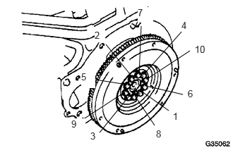
Install and uniformly tighten the 10 mounting bolts in several passes in the order shown in the illustration.
- Torque:
27 N*m (270 kgf*cm, 20 ft.*lbf)
If any of the mounting bolts does not meet the torque specification, replace the mounting bolts.
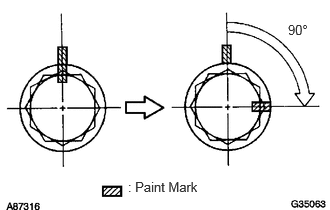
Mark the mounting bolts with paint.
Retighten the mounting bolts by 90° in the numerical order shown in the illustration.
Check that the painted marks are now at a 90° angle to their original position.
31250
20.INSTALL CLUTCH DISC ASSEMBLY
31210
21.INSTALL CLUTCH COVER ASSEMBLY
22.INSTALL ENGINE ASSEMBLY
Slowly upper the engine assembly into the engine compartment.
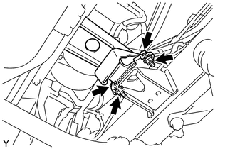
Install the No. 1 front engine mounting bracket LH with the 2 bolts and 2 nuts.
- Torque:
40 N*m (408 kgf*cm, 30 ft.*lbf)
12311
23.INSTALL NO. 1 FRONT ENGINE MOUNTING BRACKET RH
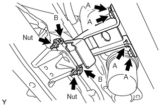
Install the No. 1 front engine mounting bracket RH with the 6 bolts and 2 nuts.
- Torque:
- Bolt A:
51 N*m (520 kgf*cm, 38 ft.*lbf)
- Bolt B:
40 N*m (408 kgf*cm, 30 ft.*lbf)
24.CONNECT ENGINE WIRE
Connect the connectors and install the wire harness clamps.
51202
25.INSTALL NO. 2 FRAME CROSSMEMBER SUB-ASSEMBLY
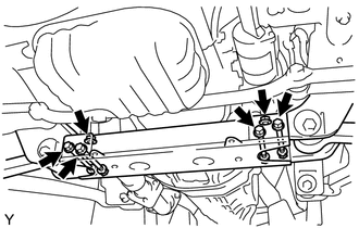
Install the No. 2 frame crossmember sub-assembly with the 6 bolts and 4 nuts.
- Torque:
160 N*m (1631 kgf*cm, 118 ft.*lbf)
45450
26.INSTALL STEERING RELAY ROD ASSEMBLY
Install the steering relay rod with the 4 nuts.
- Torque:
150 N*m (1530 kgf*cm, 111 ft.*lbf)
Install 4 new cotter pins.
33110
27.INSTALL MANUAL TRANSMISSION ASSEMBLY
28.INSTALL FUEL HOSE CLAMP
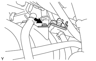
Install the fuel hose clamp with the bolt.
- Torque:
20 N*m (204 kgf*cm, 15 ft.*lbf)
23250
29.INSTALL FUEL INJECTOR ASSEMBLY
23807
30.INSTALL FUEL DELIVERY PIPE SUB-ASSEMBLY
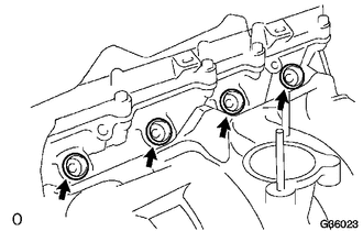
Install a new O-ring onto the injector spacer.
Install the 4 New injector spacers onto the cylinder head.
Install the 2 spacers.
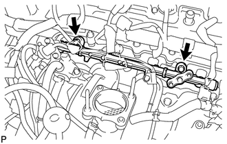
Remove the 2 bolts and fuel delivery pipe with the 4 fuel injectors.
- NOTICE:
- ·
Do not drop the fuel injector when installing the fuel delivery pipe.
·Make sure that the fuel injector turns smoothly.
Fully tighten the 2 bolts.
- Torque:
12 N*m (122 kgf*cm, 9 ft.*lbf)
23270
31.INSTALL FUEL PRESSURE PULSATION DAMPER ASSEMBLY
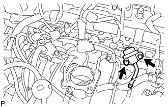
Install the pressure pulsation damper assembly with the 2 bolts.
- Torque:
9.0 N*m (92 kgf*cm, 80 in.*lbf)
23273C
32.INSTALL NO. 2 FUEL HOSE
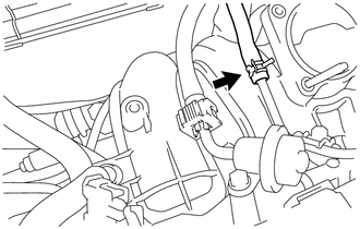
Connect the No. 2 fuel hose.
23271F
33.CONNECT FUEL HOSE
87246A
34.CONNECT HEATER WATER HOSE OUTLET E
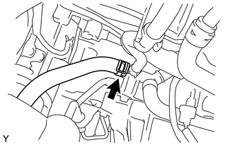
Connect the heater water hose outlet E.
87245A
35.CONNECT HEATER WATER HOSE INLET A
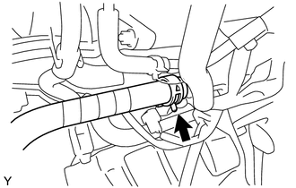
Connect the heater water hose inlet A.
44776
36.CONNECT BRAKE BOOSTER HOSE
Connect the vacuum hose onto the intake manifold.
88320
37.INSTALL COMPRESSOR AND MAGNETIC CLUTCH
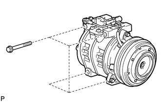
Install the compressor with the 4 bolts.
- Torque:
60 N*m (612 kgf*cm, 44 ft.*lbf)
Connect the connector.
27020
38.INSTALL GENERATOR ASSEMBLY (for 80A Type)
27020
39.INSTALL GENERATOR ASSEMBLY (for 100A Type)
44310
40.INSTALL VANE PUMP ASSEMBLY
44360
41.INSTALL VANE PUMP OIL RESERVOIR ASSEMBLY
Install the vane pump oil reservoir with the 4 bolts.
- Torque:
18 N*m (184 kgf*cm, 13 ft.*lbf)
22030
42.INSTALL THROTTLE WITH MOTOR BODY ASSEMBLY
17861
43.INSTALL INTAKE AIR CONNECTOR
17410
44.INSTALL FRONT EXHAUST PIPE ASSEMBLY
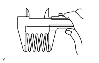
Using a vernier caliper, measure the free length of the compression spring.
- Minimum length:
41.5 mm (1.634 in.)
If the length is not as specified, replace the compression spring.
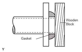
Using a plastic hammer and a wooden block, tap in a new exhaust pipe gasket until its surface is flush with the exhaust manifold.
- NOTICE:
- ·
Install the exhaust pipe gasket in the correct direction.
·Do not damage the outer surface of the exhaust pipe gasket.
·Do not reuse the exhaust pipe gasket.
·Do not push in the gasket with the exhaust pipe when connecting it.
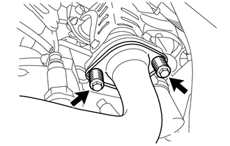
Install the front exhaust pipe assembly with the 2 compression springs and 2 bolts.
- Torque:
43 N*m (438 kgf*cm, 32 ft.*lbf)
Install a new gasket onto the front exhaust pipe assembly.
Install a new gasket onto the catalytic converter assembly.
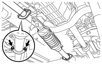
Install the catalytic converter assembly with the 2 nuts and the 2 bolts.
- Torque:
43 N*m (438 kgf*cm, 32 ft.*lbf)
16572D
45.CONNECT NO. 2 RADIATOR HOSE
16400
46.INSTALL RADIATOR ASSEMBLY
47.CONNECT CABLE FROM NEGATIVE BATTERY TERMINAL
48.ADD ENGINE OIL
49.ADD ENGINE COOLANT
50.INSPECT FOR FUEL LEAK
51.INSPECT FOR ENGINE OIL LEAK
52.INSPECT FOR COOLANT LEAK
53.INSPECT IGNITION TIMING
54.CHECK IDLE SPEED
55.CHECK CO/HC