N04C-VL ENGINE MECHANICAL CAMSHAFT INSTALLATION
PROCEDURE

 13501
1.INSTALL CAMSHAFT
Apply engine oil to the camshaft journal and bearing.
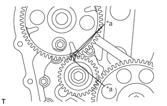
Match the alignment marks on the camshaft timing gear and oil pump gear and install the camshaft.
| *a | Alignment Mark |
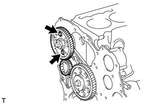
Install the camshaft with the 2 bolts.
- Torque:
29 N*m (291 kgf*cm, 21 ft.*lbf)
11301C
2.INSTALL TIMING CHAIN OR BELT COVER OIL SEAL
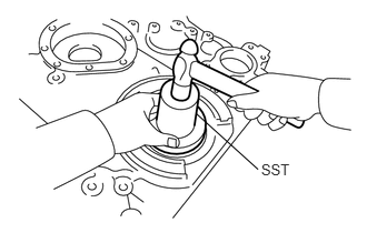
Using SST and a hammer, tap a new timing chain or belt cover oil seal into the timing gear cover until the timing chain or belt cover oil seal is flush with the timing gear edge.
- SST
- 09223-78010
- NOTICE:
- ·
Be careful not to tap the oil seal at an angle.
·Keep the gap between the gear case edge and the oil seal free of foreign matter.
Apply MP grease to the oil seal lip.
11321C
3.INSTALL TIMING GEAR COVER
Remove any old seal packing material from the contact surface.
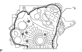
| *a | Seal Packing |
Apply seal packing in a continuous line as shown in the illustration.
- Seal packing:
Toyota Genuine Seal Packing Black, Three Bond 1207B or equivalent
- Standard seal diameter:
1.5 to 2.5 mm (0.0591 to 0.0984 in.)
- NOTICE:
- ·
Remove any oil from the contact surface.
·Install the timing gear cover within 3 minutes of applying the seal packing.
·Do not expose the seal packing to engine oil for at least 2 hours after installation.
Install the timing gear cover with the 15 bolts.
- Torque:
- 28.5 N*m (291 kgf*cm, 21 ft.*lbf)
12101
4.INSTALL OIL PAN SUB-ASSEMBLY
Remove any old seal packing material from the contact surface.
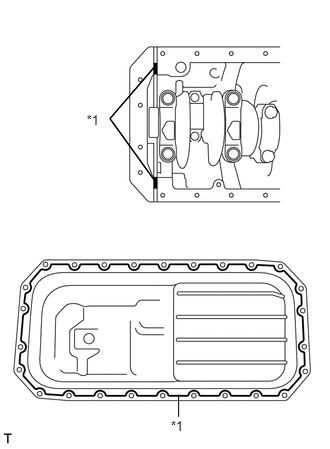
Apply a continuous bead of seal packing (diameter: 3.0 to 4.0 mm (0.118 to 0.157 in.)) as shown in the illustration.
- Seal packing:
Toyota Genuine Seal Packing Black, Three Bond 1207B or equivalent
| *1 | Seal Packing |
- NOTICE:
- ·
Remove any oil from the contact surface.
·Install the oil pan sub-assembly within 3 minutes of applying the seal packing.
·Do not expose the seal packing to engine oil for at least 2 hours after installation.
Install the oil pan sub-assembly with the 26 bolts.
- Torque:
29 N*m (291 kgf*cm, 21 ft.*lbf)
11351H
5.INSTALL FLYWHEEL HOUSING STAY RH
Install the flywheel housing stay RH with the 4 bolts.
- Torque:
- M14 bolt:
132 N*m (1346 kgf*cm, 97 ft.*lbf)
- M12 bolt:
97 N*m (989 kgf*cm, 72 ft.*lbf)
11351G
6.INSTALL FLYWHEEL HOUSING STAY LH
Install the flywheel housing stay LH with the 4 bolts.
- Torque:
- M14 bolt:
132 N*m (1346 kgf*cm, 97 ft.*lbf)
- M12 bolt:
97 N*m (989 kgf*cm, 72 ft.*lbf)
13470
7.INSTALL CRANKSHAFT PULLEY ASSEMBLY
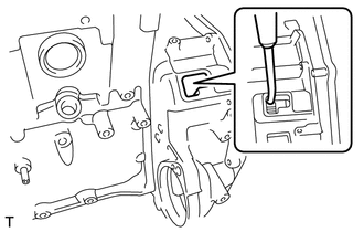
Install the crankshaft pulley and crankshaft pulley spacer onto the crankshaft.
- HINT:
-
Align the pulley set key with the key groove of the pulley.
Using a 46 mm socket wrench, tighten the nut.
- Torque:
100 N*m (1020 kgf*cm, 74 ft.*lbf)
- HINT:
-
Insert a screwdriver through the inspection hole of the flywheel housing into the ring gear of the flywheel to keep it from turning together with the crankshaft.
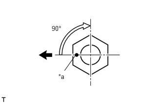
Mark the front side of the nut with paint as shown in the illustration.
| *a | Paint |

|
Front Side of Engine |
Retighten the nut by 90°.
13751
8.INSTALL VALVE LIFTER
- NOTICE:
-
Be sure to install the valve lifter to its original position.
11115
9.INSTALL CYLINDER HEAD GASKET
11101
10.INSTALL CYLINDER HEAD SUB-ASSEMBLY
13819
11.INSTALL VALVE BRIDGE
13781
12.INSTALL VALVE PUSH ROD
13901
13.INSTALL NO. 1 VALVE ROCKER SHAFT SUB-ASSEMBLY
14.ADJUST VALVE CLEARANCE
16206A
15.INSTALL NO. 2 WATER BY-PASS PIPE SUB-ASSEMBLY
12204
16.INSTALL VENTILATION VALVE SUB-ASSEMBLY
29300
17.INSTALL VACUUM PUMP ASSEMBLY
29601B
18.INSTALL VACUUM PUMP OIL PIPE SUB-ASSEMBLY
19971E
19.INSTALL VACUUM PIPE
20.INSTALL CAMSHAFT POSITION SENSOR
27020
21.INSTALL GENERATOR ASSEMBLY
16100
22.INSTALL ENGINE WATER PUMP ASSEMBLY
88420
23.INSTALL IDLE PULLEY ASSEMBLY WITH BRACKET (w/ Air Conditioning System)
16630G
24.INSTALL IDLER PULLEY ASSEMBLY
88431
25.INSTALL NO. 1 COMPRESSOR MOUNTING BRACKET (w/ Air Conditioning System)
88320
26.INSTALL COOLER COMPRESSOR ASSEMBLY (w/ Air Conditioning System)
16206
27.INSTALL WATER BY-PASS PIPE SUB-ASSEMBLY
16206B
28.INSTALL NO. 3 WATER BY-PASS PIPE SUB-ASSEMBLY
87208L
29.INSTALL WATER PIPE SUB-ASSEMBLY
87245B
30.CONNECT INLET HEATER WATER HOSE B
87246B
31.CONNECT OUTLET HEATER WATER HOSE B
16577C
32.INSTALL RADIATOR PIPE
22100
33.INSTALL INJECTION OR SUPPLY PUMP ASSEMBLY
23670
34.INSTALL INJECTOR ASSEMBLY
17201
35.INSTALL TURBOCHARGER SUB-ASSEMBLY
16400
36.INSTALL RADIATOR ASSEMBLY