STEERING COLUMN STEERING COLUMN ASSEMBLY(for LHD) INSTALLATION
CAUTION / NOTICE / HINT
- HINT:
-
A bolt without a torque specification is shown in the standard bolt chart (See page General>SPECIFICATIONS>STANDARD BOLT>SPECIFIED TORQUE FOR STANDARD BOLTS).
PROCEDURE

 1.ALIGN FRONT WHEELS FACING STRAIGHT AHEAD
45260
2.INSTALL NO. 2 STEERING INTERMEDIATE SHAFT ASSEMBLY
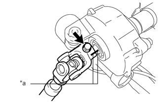
Align the matchmarks on the No. 2 steering intermediate shaft assembly and steering column assembly.
| *a | Matchmark |
Install the No. 2 steering intermediate shaft assembly to the steering column assembly.
Install the bolt.
- Torque:
- 35 N*m (360 kgf*cm, 26 ft.*lbf)
3.INSTALL STEERING COLUMN ASSEMBLY
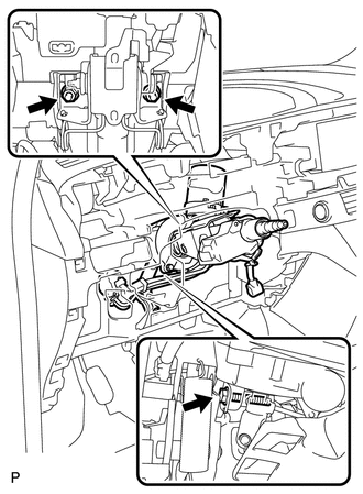
Install the steering column assembly with the bolt and 2 nuts.
- Torque:
- Bolt : 36 N*m (370 kgf*cm, 26 ft.*lbf)
- Nut : 25 N*m (255 kgf*cm, 18 ft.*lbf)
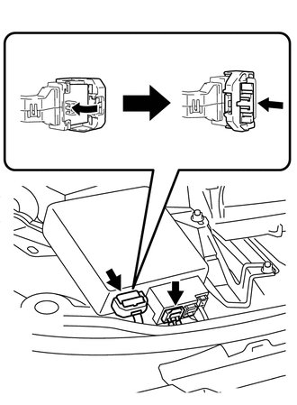
Connect the 2 connectors to the power steering ECU assembly.
Connect each connector and engage each wire harness clamp to the steering column assembly.
45260
4.CONNECT NO. 2 STEERING INTERMEDIATE SHAFT ASSEMBLY
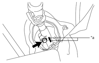
Align the matchmarks on the No. 2 steering intermediate shaft assembly and steering intermediate shaft assembly.
| *a | Matchmark |
Connect the No. 2 steering intermediate shaft assembly to the steering intermediate shaft assembly.
Install the bolt.
- Torque:
- 35 N*m (360 kgf*cm, 26 ft.*lbf)
45259A
5.INSTALL COLUMN HOLE COVER SILENCER SHEET
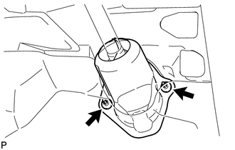
Install the column hole cover silencer sheet with the 2 clips.
Return the floor carpet to its original position.
55432B
6.INSTALL INSTRUMENT PANEL FINISH PANEL LOWER (w/ Driver Side Knee Airbag)
55432B
7.INSTALL INSTRUMENT PANEL FINISH PANEL LOWER (w/o Driver Side Knee Airbag)
55606
8.INSTALL NO. 1 INSTRUMENT PANEL UNDER COVER SUB-ASSEMBLY
62112
9.INSTALL COWL SIDE TRIM BOARD LH
67914B
10.INSTALL FRONT DOOR SCUFF PLATE LH
55446A
11.INSTALL NO. 1 SWITCH HOLE BASE
55302A
12.INSTALL UPPER INSTRUMENT PANEL SUB-ASSEMBLY
13.INSTALL TURN SIGNAL SWITCH ASSEMBLY WITH SPIRAL CABLE
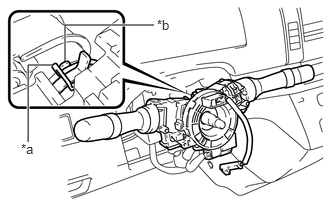
Using pliers, expand the clamp.
| *a | Clamp |
| *b | Claw |
While holding the clamp expanded, install the turn signal switch assembly with spiral cable to the steering column assembly and engage the claw.
Return the clamp to its original position.
Connect each connector to the turn signal switch assembly with spiral cable.
45286
14.INSTALL STEERING COLUMN COVER
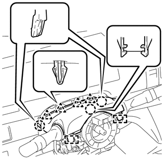
Engage the 3 claws, 4 clips, and 2 pins to install the steering column cover (upper side).
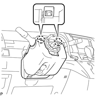
Engage the 2 claws to install the steering column cover (lower side).
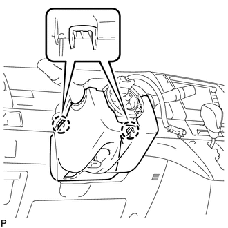
Engage the 2 claws.
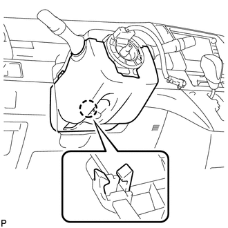
Engage the claw.
- HINT:
-
Press the area around the claw to engage it.
15.ALIGN FRONT WHEELS FACING STRAIGHT AHEAD
84306
16.POSITION SPIRAL CABLE
45100
17.INSTALL STEERING WHEEL ASSEMBLY
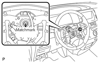
Align the matchmarks and install the steering wheel assembly onto the steering column assembly.
Install the nut.
- Torque:
- 50 N*m (510 kgf*cm, 37 ft.*lbf)
Connect each connector to the spiral cable.
18.CHECK STEERING WHEEL CENTER POINT
45130
19.INSTALL STEERING PAD ASSEMBLY
20. TORQUE SENSOR ZERO POINT CALIBRATION