2011-2016 FJ Cruiser · Service Manual BRAKE

TRC OFF Indicator Light Remains ON

Circuit diagnosis · Vehicles built Aug 2008 – Jul 2009

Versions by build date: Aug 2008 – Jul 2009 Aug 2009 – Oct 2010 Nov 2010 – Jul 2011 Aug 2011 – Jul 2012 Aug 2012 – Oct 2012 Nov 2012 – Jul 2014 from Aug 2014

DESCRIPTION

The TRAC OFF indicator will come on in any of the following conditions:
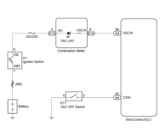
The transfer indicator switch (L4 position) is turned on, the rear differential switch is turned on, the VSC OFF switch is turned on (w/o auto LSD), or the VSC OFF switch is held down for 3 seconds (w/ auto LSD).

WIRING DIAGRAM

C164949E08

INSPECTION PROCEDURE

NOTICE:
  1. Before troubleshooting, check that the rear differential switch circuit, the transfer indicator switch (L4 position) circuit, and the VSC OFF switch circuit are all off.
  2. When replacing the master cylinder solenoid, perform zero point calibration (Click here).


1. CHECK SKID CONTROL ECU CONNECTOR
  1. Check that the ECU connector is securely connected.
    OK:
    The connector is securely connected.


NG
CONNECT CONNECTOR CORRECTLY
OK


2. INSPECT VSC OFF SWITCH

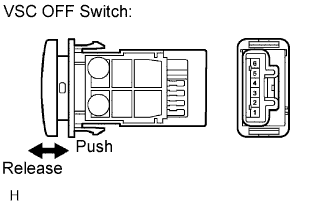
  1. I044055E14
    Remove the VSC OFF switch (Click here).

  1. Disconnect the VSC OFF switch connector.

  1. Measure the resistance.

    Standard resistance:
    Tester Connection
    Switch Condition
    Specified Condition
    3-4
    Released
    10 kΩ or higher
    3-4
    Pushed in
    Below 1 Ω


NG
REPLACE VSC OFF SWITCH (Click here)
OK


3. CHECK HARNESS AND CONNECTOR (SKID CONTROL ECU - VSC OFF SWITCH)

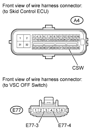
  1. C138448E04
    Disconnect the skid control ECU connector.

  1. Disconnect the VSC OFF switch connector.

  1. Measure the resistance according to the value(s) in the table below.

    Standard resistance:
    Tester Connection
    Condition
    Specified Condition
    A4-43 (CSW) - E77-3
    Always
    Below 1 Ω
    A4-43 (CSW) - Body ground
    Always
    10 kΩ or higher
    E3-77 - Body ground
    Always
    Below 1 Ω


NG
REPAIR OR REPLACE HARNESS OR CONNECTOR
OK


4. CHECK HARNESS AND CONNECTOR (SKID CONTROL ECU - COMBINATION METER)

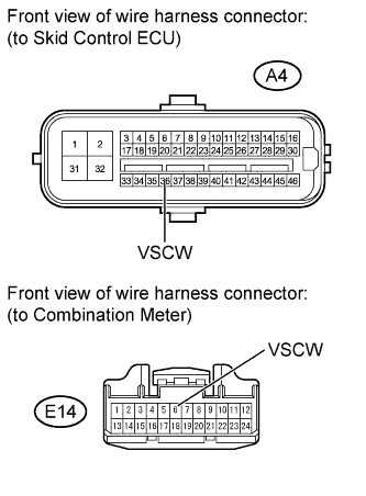
  1. C135294E06
    Disconnect the skid control ECU connector.

  1. Disconnect the combination meter connector.

  1. Measure the resistance according to the value(s) in the table below.

    Standard resistance:
    Tester Connection
    Switch Condition
    Specified Condition
    A4-36 (VSCW) - E14-6 (VSCW)
    Always
    Below 1 Ω
    A4-36 (VSCW) - Body ground
    Always
    10 kΩ or higher


NG
REPAIR OR REPLACE HARNESS OR CONNECTOR
OK


5. INSPECT COMBINATION METER ASSEMBLY
  1. Check the combination meter system (Click here).

    OK:
    Combination meter is normal.


NG
REPLACE COMBINATION METER ASSEMBLY (Click here)
OK

REPLACE MASTER CYLINDER SOLENOID (Click here)


← Brake Warning Light does not Come ON (from Aug 2011)TRC OFF Indicator Light Remains ON (Aug 2009 – Oct 2010) →