HEATING / AIR CONDITIONING FRONT AIR CONDITIONING UNIT REMOVAL
PROCEDURE

 1. PRECAUTION
- NOTICE:
-
Make sure to select face mode before disconnecting the cable from the negative (-) battery terminal.
Click herePower Source / Network>POWER DISTRIBUTION>MAIN BODY ECU>REMOVAL
2.DISCONNECT CABLE FROM NEGATIVE BATTERY TERMINAL
3.RECOVER REFRIGERANT FROM REFRIGERATION SYSTEM
85292B
4.REMOVE FRONT WIPER ARM HEAD CAP
5.REMOVE FRONT WIPER ARM AND BLADE ASSEMBLY LH
6.REMOVE FRONT WIPER ARM AND BLADE ASSEMBLY RH
53867H
7.REMOVE FRONT FENDER TO COWL SIDE SEAL LH
53866J
8.REMOVE FRONT FENDER TO COWL SIDE SEAL RH
55781E
9.REMOVE COWL TOP VENTILATOR LOUVER SUB-ASSEMBLY
10.REMOVE WINDSHIELD WIPER MOTOR AND LINK ASSEMBLY (for 2GR-FKS)
55701J
11.REMOVE OUTER COWL TOP PANEL SUB-ASSEMBLY (for 2GR-FKS)
for LHD:
Click hereSuspension>FRONT SUSPENSION>FRONT SHOCK ABSORBER>REMOVAL
for RHD:
Click hereSuspension>FRONT SUSPENSION>FRONT SHOCK ABSORBER>REMOVAL
88704
12.DISCONNECT SUCTION HOSE SUB-ASSEMBLY
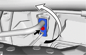
Remove the bolt and rotate the hook connector as shown in the illustration.
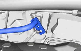
Disconnect the suction hose sub-assembly.
Remove the O-ring from the suction hose sub-assembly.
- NOTICE:
-
Seal the openings of the disconnected parts using vinyl tape to prevent entry of moisture and foreign matter.
13.DISCONNECT AIR CONDITIONER TUBE AND ACCESSORY ASSEMBLY
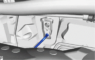
Disconnect the air conditioner tube and accessory assembly.
Remove the O-ring from the air conditioner tube and accessory assembly.
- NOTICE:
-
Seal the openings of the disconnected parts using vinyl tape to prevent entry of moisture and foreign matter.
87246
14.DISCONNECT OUTLET HEATER WATER HOSE
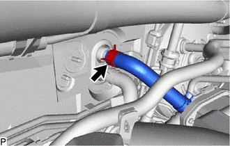
Using pliers, grip the claws of the clip and slide the clip to disconnect the outlet heater water hose.
- NOTICE:
- ·
Do not apply excessive force to the outlet heater water hose.
·Prepare a drain pan or cloth in case the coolant leaks.
87245
15.DISCONNECT INLET HEATER WATER HOSE
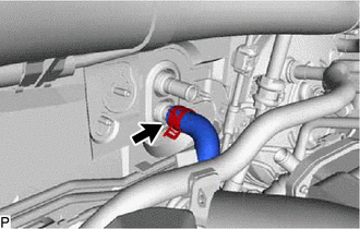
Using pliers, grip the claws of the clip and slide the clip to disconnect the inlet heater water hose.
- NOTICE:
- ·
Do not apply excessive force to the inlet heater water hose.
·Prepare a drain pan or cloth in case the coolant leaks.
16.REMOVE FRONT SEAT ASSEMBLY LH (for Manual Seat)
17.REMOVE FRONT SEAT ASSEMBLY LH (for Power Seat)
18.REMOVE FRONT SEAT ASSEMBLY RH (for Manual Seat)
- HINT:
-
Use the same procedure as for the LH side.
19.REMOVE FRONT SEAT ASSEMBLY RH (for Power Seat)
- HINT:
-
Use the same procedure as for the LH side.
20.REMOVE INSTRUMENT PANEL SAFETY PAD SUB-ASSEMBLY
21.REMOVE STEERING POST ASSEMBLY
82877
22.REMOVE ECU INTEGRATION BOX RH (for LHD)
82878
23.REMOVE ECU INTEGRATION BOX LH (for RHD)
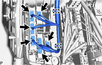
Disconnect each connector.
Disengage the 2 clamps.
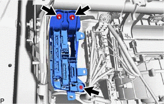
Remove the bolt, 2 nuts and ECU integration box LH.
88650N
24.REMOVE AIR CONDITIONING AMPLIFIER ASSEMBLY
25.REMOVE INSTRUMENT PANEL JUNCTION BLOCK ASSEMBLY WITH MAIN BODY ECU
for LHD:
Click herePower Source / Network>POWER DISTRIBUTION>MAIN BODY ECU>REMOVAL
for RHD:
Click herePower Source / Network>POWER DISTRIBUTION>MAIN BODY ECU>REMOVAL
26.REMOVE WIRE HARNESS CLAMP BRACKET (for LHD)
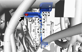
Disengage the 3 clamps.
Remove the nut and wire harness clamp bracket.
88625Q
27.REMOVE COOLER (ROOM TEMP. SENSOR) THERMISTOR (for Automatic Air Conditioning System)
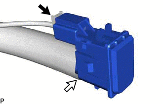
Disconnect the connector and aspirator to remove the cooler (room temp. sensor) thermistor.
87213
28.REMOVE REAR NO. 2 AIR DUCT
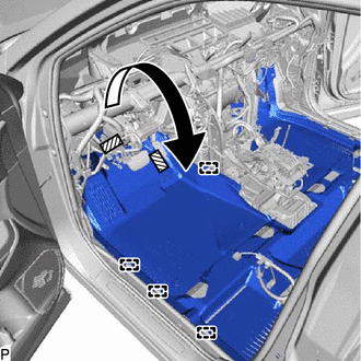

|
Fastener |
Disengage 4 guides and 2 fasteners, and turn back the front floor carpet assembly as shown in the illustration.
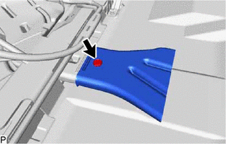
Remove the clip and rear No. 2 air duct.
87212
29.REMOVE REAR NO. 1 AIR DUCT
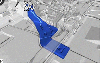
Disengage the clamp to disconnect the wire harness.
Disengage the 2 claws and remove the rear No. 1 air duct.
87215D
30.REMOVE REAR NO. 4 AIR DUCT
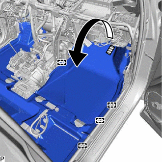
|
|
Fastener |
Disengage the 4 guides and fastener, and turn back the front floor carpet assembly as shown in the illustration.
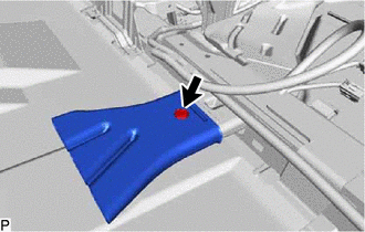
Remove the clip and rear No. 4 air duct.
87214D
31.REMOVE REAR NO. 3 AIR DUCT
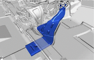
Disengage the 2 claws and remove the rear No. 3 air duct.
33550
32.REMOVE TRANSMISSION FLOOR SHIFT ASSEMBLY
for U760E Automatic Transmission / Transaxle:
Click hereDrivetrain>U760E AUTOMATIC TRANSMISSION / TRANSAXLE>SHIFT LEVER>REMOVAL
for UA80E Automatic Transmission / Transaxle:
Click hereDrivetrain>UA80E (AUTOMATIC TRANSMISSION / TRANSAXLE)>SHIFT LEVER>REMOVAL
for UA80F Automatic Transmission / Transaxle:
Click hereDrivetrain>UA80F (AUTOMATIC TRANSMISSION / TRANSAXLE)>SHIFT LEVER>REMOVAL
33525
33.REMOVE SHIFT LEVER SUPPORT
Disconnect each connector.
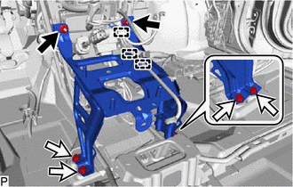

|
Nut |

|
Bolt |
Disengage each clamp.
Remove the 2 nuts, 4 bolts and shift lever support.
85940
34.REMOVE WINDSHIELD WIPER RELAY ASSEMBLY (w/ Rain Sensor)
88150A
35.REMOVE DRIVING SUPPORT ECU ASSEMBLY (for RHD)
w/ Toyota Safety Sense P
Click hereEngine / Hybrid System>CRUISE CONTROL>DRIVING SUPPORT ECU(for RHD)>REMOVAL
55306A
36.REMOVE NO. 1 INSTRUMENT PANEL BRACE SUB-ASSEMBLY
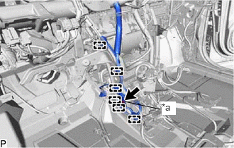
| *a | Earth Wire |
Disengage each clamp.
Remove the bolt and disconnect the earth wire.
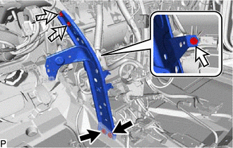
|
|
Bolt |
|
|
Screw |

|
Nut |
Remove the 2 bolts, screw, 2 nuts and No. 1 instrument panel brace sub-assembly.
55307C
37.REMOVE NO. 2 INSTRUMENT PANEL BRACE SUB-ASSEMBLY
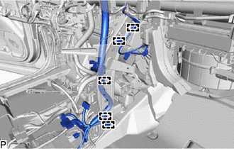
Disengage each clamp.
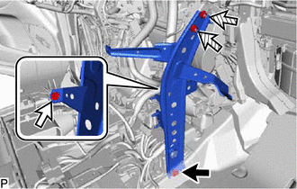
|
|
Bolt |
|
|
Screw |
|
|
Nut |
Remove the bolt, screw, 2 nuts and No. 2 instrument panel brace sub-assembly.
55458A
38.REMOVE INSTRUMENT PANEL SAFETY PAD CAP
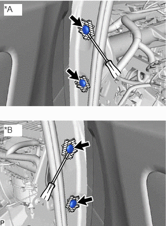
| *A | for LH Side |
| *B | for RH Side |
|
|
Protective Tape |
Put protective tape around the 4 instrument panel safety pad caps.
Using a screwdriver, remove the 4 instrument panel safety pad caps.
39.REMOVE INSTRUMENT PANEL REINFORCEMENT ASSEMBLY WITH AIR CONDITIONING UNIT
- NOTICE:
- ·
Be sure to support the air conditioning unit assembly when removing it. Failure to do so may cause the bracket of the air conditioning unit assembly to break.
·When disassembling the air conditioning unit assembly, eliminate static electricity by touching the vehicle body to prevent the components from being damaged.
for LHD:
Remove the 4 bolts and disconnect the 4 earth wires.
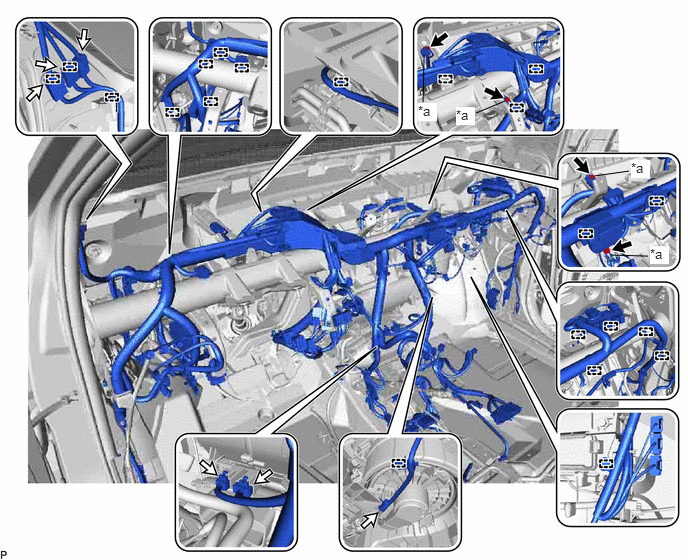
| *a | Earth Wire | - | - |
Disconnect each connector.
Disengage each clamp.
for RHD:
Remove the 3 bolts and disconnect the 3 earth wires.
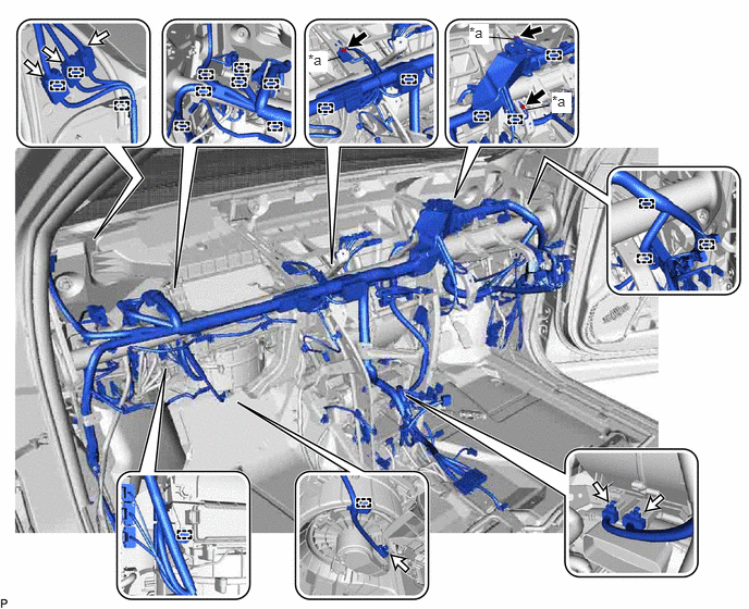
| *a | Earth Wire | - | - |
Disconnect each connector.
Disengage each clamp.
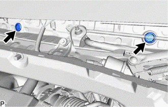
Remove the 2 hole plugs.
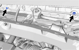
Remove the 2 bolts.
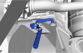
Disengage the claw and disconnect the drain cooler hose from the piping clamp.
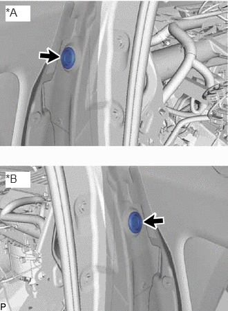
| *A | for LH Side |
| *B | for RH Side |
Remove the 2 hole plugs.
Disconnect the drain cooler hose.
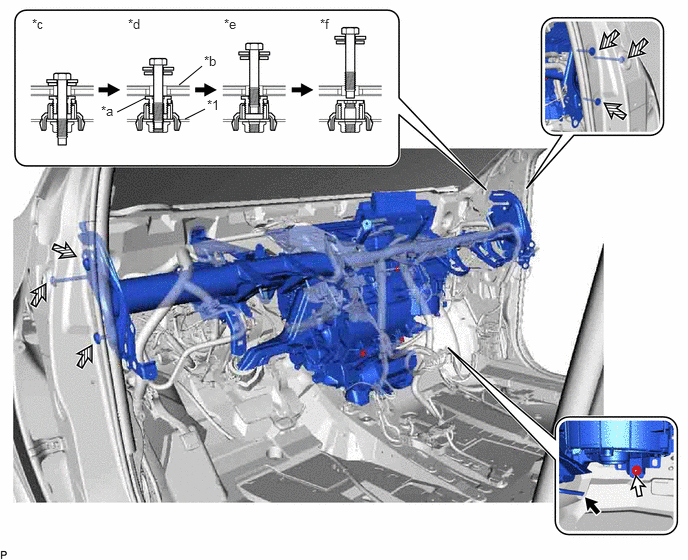
| *1 | Instrument Panel Reinforcement Assembly | - | - |
| *a | Movable Collar | *b | Vehicle Body |
| *c | Step 1 | *d | Step 2 |
| *e | Step 3 | *f | Step 4 |
|
|
Nut |
|
Bolt |
Remove the nut and 6 bolts as shown in the illustration.
Disengage the 3 guides and remove the instrument panel reinforcement assembly with air conditioning unit as shown in the illustration.
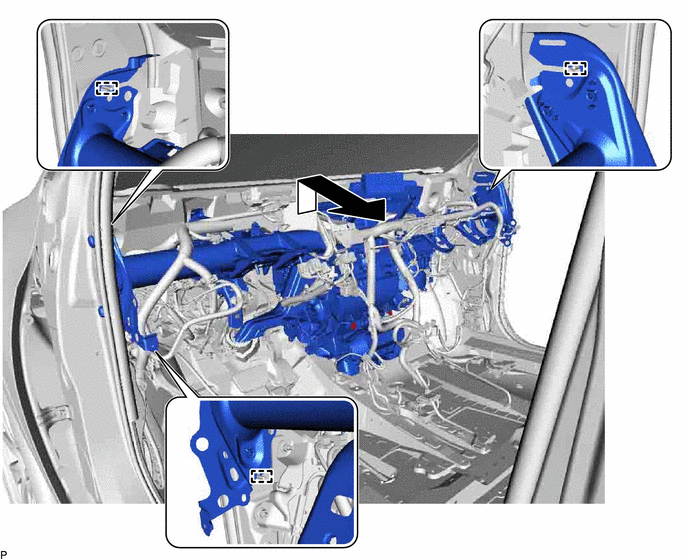
40.REMOVE AIR CONDITIONING UNIT ASSEMBLY
Remove the 3 bolts.
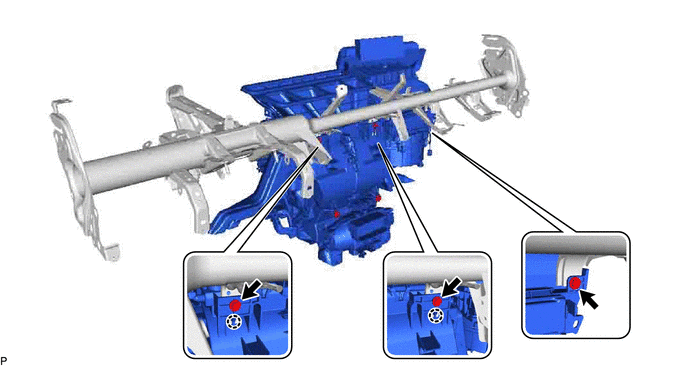
Disengage the 2 claws to remove the air conditioning unit assembly from the instrument panel reinforcement assembly.