FRONT SUSPENSION FRONT SUSPENSION MEMBER(When Using the Engine Support Bridge for 1AR-FE) INSTALLATION
PROCEDURE

 1.INSTALL HOLE PLUG
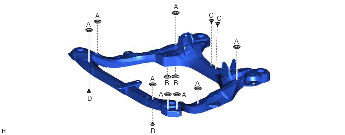
Install the 14 hole plugs to the front frame assembly.
- HINT:
-
There are 4 different shapes of hole plug.
52217E
2.INSTALL FRONT SUSPENSION MEMBER BODY MOUNTING REAR CUSHION LH
| *a | View from Underneath |

|
Front of the Vehicle |
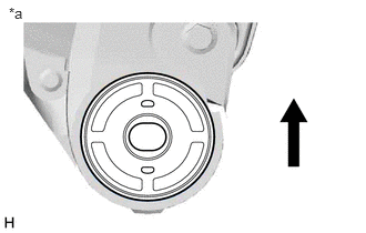
Temporarily install a new front suspension member body mounting rear cushion LH while confirming the installation direction.
- NOTICE:
-
Position the front suspension member body mounting rear cushion LH in the correct direction.
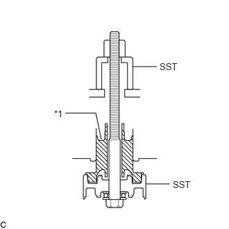
| *1 | Front Suspension Member Body Mounting Rear Cushion LH |
Install SST as shown in the illustration.
- SST
- 09830-10010 (09830-01010, 09830-01020, 09830-01030, 09830-01060)
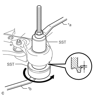
| *a | Hold |
| *b | Turn |
Using SST, install the front suspension member body mounting rear cushion LH as shown in the illustration.
- NOTICE:
-
Check that there is no clearance between the front frame assembly and the front suspension member body mounting rear cushion LH.
52215
3.INSTALL FRONT SUSPENSION MEMBER BODY MOUNTING REAR CUSHION RH
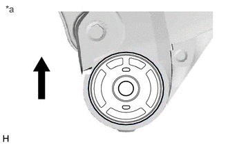
| *a | View from Underneath |
|
|
Front of the Vehicle |
Temporarily install a new front suspension member body mounting rear cushion RH while confirming the installation direction.
- NOTICE:
-
Position the front suspension member body mounting rear cushion RH in the correct direction.
Install SST using the same procedure as for the front suspension member body mounting rear cushion LH.
- SST
- 09830-10010 (09830-01010, 09830-01020, 09830-01030, 09830-01060)
Using SST, install the front suspension member body mounting rear cushion RH.
- SST
- 09830-10010 (09830-01010, 09830-01020, 09830-01030, 09830-01060)
- HINT:
-
Perform the same procedure as for the LH side.
52211J
4.INSTALL FRONT SUSPENSION MEMBER BODY MOUNTING FRONT CUSHION
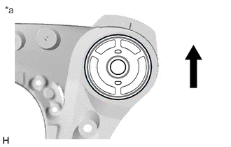
| *a | View from Underneath |
|
|
Front of the Vehicle |
Temporarily install a new front suspension member body mounting front cushion while confirming the installation direction.
- NOTICE:
-
Position the front suspension member body mounting front cushion in the correct direction.
Install SST using the same procedure as for the front suspension member body mounting rear cushion LH.
- SST
- 09830-10010 (09830-01010, 09830-01020, 09830-01030, 09830-01060)
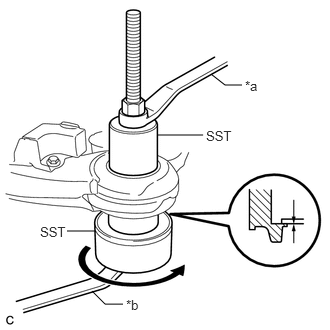
| *a | Hold |
| *b | Turn |
Using SST, install each front suspension member body mounting front cushion as shown in the illustration.
- SST
- 09830-10010 (09830-01010, 09830-01020, 09830-01030, 09830-01060)
- NOTICE:
-
Check that there is no clearance between the front frame assembly and the front suspension member body mounting front cushion.
52216B
5.INSTALL FRONT SUSPENSION MEMBER BODY MOUNTING REAR STOPPER
Install the 2 front suspension member body mounting rear stoppers to the front frame assembly.
52213A
6.INSTALL FRONT SUSPENSION MEMBER BODY MOUNTING FRONT STOPPER
Install the 2 front suspension member body mounting front stoppers to the front frame assembly.
51227B
7.INSTALL FRONT SUSPENSION MEMBER DYNAMIC DAMPER
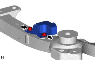
Install the front suspension member dynamic damper to the front frame assembly with the 2 bolts.
- Torque:
- 29 N*m (296 kgf*cm, 21 ft.*lbf)
48069
8.INSTALL FRONT LOWER NO. 1 SUSPENSION ARM SUB-ASSEMBLY LH
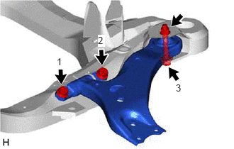
Install the front lower No. 1 suspension arm sub-assembly LH to the front frame assembly with the 3 bolts and nut in the order shown in the illustration.
- Torque:
- Bolt (1), (2) : 200 N*m (2039 kgf*cm, 148 ft.*lbf)
- Bolt (3) : 135 N*m (1377 kgf*cm, 100 ft.*lbf)
- NOTICE:
-
Because the nut has its own stopper, do not turn the nut. Tighten the bolt with the nut secured.
48068
9.INSTALL FRONT LOWER NO. 1 SUSPENSION ARM SUB-ASSEMBLY RH
- HINT:
-
Perform the same procedure as for the LH side.
10.INSTALL STEERING LINK ASSEMBLY
Install the steering link assembly to the front frame assembly with the 2 bolts and 2 nuts.
- Torque:
- 70 N*m (714 kgf*cm, 52 ft.*lbf)
- NOTICE:
- ·
Make sure to tighten the bolts starting from the steering link assembly pinion shaft side.
·Keep the nut from rotating while turning the bolt because the nut has its own stopper.
11.INSTALL FRONT STABILIZER BAR WITH FRONT STABILIZER LINK ASSEMBLY
Install the front stabilizer bar with 2 front No. 2 stabilizer brackets, 2 front No. 1 stabilizer bar bushings and 2 front stabilizer link assemblies to the front frame assembly.
48829A
12.INSTALL FRONT NO. 1 STABILIZER BRACKET LH
Install the front No. 1 stabilizer bracket LH to the front frame assembly with the 2 bolts.
- Torque:
- 29 N*m (296 kgf*cm, 21 ft.*lbf)
48824A
13.INSTALL FRONT NO. 1 STABILIZER BRACKET RH
- HINT:
-
Perform the same procedure as for the LH side.
51100G
14.INSTALL FRONT FRAME ASSEMBLY
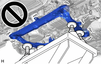
Slowly jack up the front frame assembly with an engine lifter using 4 attachments or equivalent tools.
- CAUTION:
-
- ·
The front frame assembly is a very heavy component. Make sure that it is supported securely.
·If the front frame assembly is not securely supported, it may drop, resulting in serious injury.
- NOTICE:
-
Use attachments to keep the front frame assembly level.
Install the front frame assembly to the vehicle body.
|
|
Bolt |

|
Nut |
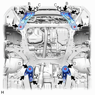
Install the frame side rail plate RH and frame side rail plate LH with the 6 bolts and 2 nuts.
- Torque:
- Bolt (A) : 85 N*m (867 kgf*cm, 63 ft.*lbf)
- Bolt (B) : 32 N*m (326 kgf*cm, 24 ft.*lbf)
- Nut (C) : 32 N*m (326 kgf*cm, 24 ft.*lbf)
Install the front suspension member rear brace RH and front suspension member rear brace LH with the 6 bolts and 2 nuts.
- Torque:
- Bolt (D) : 85 N*m (867 kgf*cm, 63 ft.*lbf)
- Bolt (E) : 32 N*m (326 kgf*cm, 24 ft.*lbf)
- Nut (F) : 32 N*m (326 kgf*cm, 24 ft.*lbf)
Lower the engine lifter.
15.REMOVE BELT
16.REMOVE ENGINE SUPPORT BRIDGE
17.REMOVE ENGINE HANGERS
12327A
18.INSTALL NO. 2 ENGINE MOUNTING STAY RH
12361
19.CONNECT FRONT ENGINE MOUNTING INSULATOR
Connect the front engine mounting insulator to the front frame assembly with the 3 nuts.
- Torque:
- 58 N*m (591 kgf*cm, 43 ft.*lbf)
Install the hole plug.
12372A
20.CONNECT ENGINE MOUNTING INSULATOR LH
Connect the engine mounting insulator LH to the front frame assembly with the 3 nuts.
- Torque:
- 99 N*m (1010 kgf*cm, 73 ft.*lbf)
Install the 2 hole plugs.
12362
21.CONNECT ENGINE MOUNTING INSULATOR RH
Connect the engine mounting insulator RH to the front frame assembly with the 3 nuts.
- Torque:
- 99 N*m (1010 kgf*cm, 73 ft.*lbf)
Install the 2 hole plugs.
17410
22.INSTALL FRONT EXHAUST PIPE ASSEMBLY
48069
23.CONNECT FRONT LOWER NO. 1 SUSPENSION ARM SUB-ASSEMBLY LH
48068
24.CONNECT FRONT LOWER NO. 1 SUSPENSION ARM SUB-ASSEMBLY RH
- HINT:
-
Perform the same procedure as for the LH side.
45470
25.CONNECT TIE ROD ASSEMBLY LH
45460
26.CONNECT TIE ROD ASSEMBLY RH
- HINT:
-
Perform the same procedure as for the LH side.
45220
27.CONNECT STEERING INTERMEDIATE SHAFT ASSEMBLY
48810
28.CONNECT FRONT STABILIZER LINK ASSEMBLY LH
48820B
29.CONNECT FRONT STABILIZER LINK ASSEMBLY RH
- HINT:
-
Perform the same procedure as for the LH side.
82121
30.CONNECT ENGINE WIRE
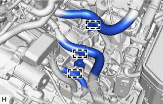
Connect the 3 wire clamps.
28800
31.INSTALL BATTERY
47220D
32.INSTALL BRAKE MASTER CYLINDER RESERVOIR ASSEMBLY
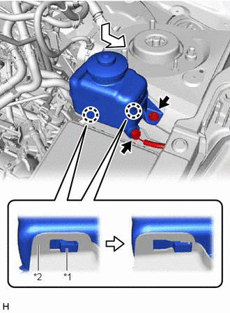
| *1 | Brake Master Cylinder Reservoir Assembly |
| *2 | Reservoir Bracket |
Move the brake master cylinder reservoir assembly as shown in the illustration to engage the 2 claws.
Connect the reservoir level switch connector and install the bolt.
- Torque:
- 9.0 N*m (92 kgf*cm, 80 in.*lbf)
17701
33.INSTALL AIR CLEANER CASE SUB-ASSEMBLY
17801
34.INSTALL AIR CLEANER FILTER ELEMENT SUB-ASSEMBLY
17705
35.INSTALL AIR CLEANER CAP WITH AIR CLEANER HOSE
17750A
36.INSTALL INLET AIR CLEANER ASSEMBLY
12601B
37.INSTALL NO. 1 ENGINE COVER SUB-ASSEMBLY
53295E
38.INSTALL COOL AIR INTAKE DUCT SEAL
53298E
39.INSTALL RADIATOR SIDE SEAL RH
53299D
40.INSTALL RADIATOR SIDE DEFLECTOR SEAL LH
41.INSTALL OUTER COWL TOP PANEL SUB-ASSEMBLY
42.INSTALL WINDSHIELD WIPER MOTOR AND LINK ASSEMBLY
43.CONNECT CABLE TO NEGATIVE BATTERY TERMINAL
- NOTICE:
-
When disconnecting the cable, some systems need to be initialized after the cable is reconnected.
-
Click hereGeneral>INTRODUCTION>REPAIR INSTRUCTION>INITIALIZATION
44.INSPECT FOR EXHAUST GAS LEAK
53737B
45.INSTALL FRONT FENDER APRON SEAL LH
53736
46.INSTALL FRONT FENDER APRON SEAL RH
53876A
47.INSTALL FRONT FENDER LINER LH
53875A
48.INSTALL FRONT FENDER LINER RH
58166
49.INSTALL FRONT FLOOR COVER LH
51442
50.INSTALL NO. 2 ENGINE UNDER COVER
51441
51.INSTALL NO. 1 ENGINE UNDER COVER
52.INSTALL FRONT WHEELS
- Torque:
- 103 N*m (1050 kgf*cm, 76 ft.*lbf)
53.INSPECT AND ADJUST FRONT WHEEL ALIGNMENT
54.INSPECT SPEED SENSOR SIGNAL