2GR-FKS ENGINE MECHANICAL CAMSHAFT REMOVAL
CAUTION / NOTICE / HINT
The necessary procedures (adjustment, calibration, initialization or registration) that must be performed after parts are removed and installed, or replaced during camshaft removal/installation are shown below.
| Replaced Part or Performed Procedure | Necessary Procedure | Effect/Inoperative Function when Necessary Procedure not Performed | Link |
|---|---|---|---|
|
*1: Learning can also be performed using the GTS. Click here( *2: Not necessary when ECM replaced with new one *3: Even when not replacing the part, it is necessary to perform the specified necessary procedures after installation. *4: If the vehicle height has changed due to suspension or tire replacement *5: When the starter assembly is replaced, "ST relay" must be also replaced |
|||
| Battery terminal is disconnected/reconnected | Idle the engine for approximately 5 to 60 minutes or drive the vehicle until stop and start control is permitted | Stop and Start System | ( ) |
| Perform steering sensor zero point calibration | Lane Control System | ()
|
|
| Parking Support Brake System*1 | |||
| Pre-collision System | |||
| Memorize steering angle neutral point | Parking Assist Monitor System | ()
|
|
| Panoramic View Monitor System | ()
|
||
| Initialize back door lock | Power Door Lock Control System | ()
|
|
| Reset back door close position | Power Back Door System | ()
|
|
| Replacement of ECM | Perform Vehicle Identification Number (VIN) or frame number registration | DTC is output | ()
|
| Code registration | Engine start function | See Service Bulletin for the registration method | |
·
Replacement of throttle body with motor assembly ·
Cleaning the deposits from the throttle body with motor assembly ·
Replacement of camshaft (for intake or exhaust camshaft) ·
Replacement of camshaft timing gear assembly ·
Replacement of camshaft timing exhaust gear assembly ·
Replacement of fuel injector assembly (for port injection) ·
Replacement of fuel injector assembly (for direct injection) ·
Replacement of fuel pump assembly (for high pressure side) ·
Replacement of ignition coil assembly ·
Air leaks from intake system ·
Gas leak from exhaust system is repaired |
Perform Inspection After Repair | ·
Poor idle, etc. ·
Engine start function, etc. |
()
|
| Replacement of automatic transaxle assembly | ·
Perform reset memory ·
Input transaxle compensation code into ECM ·
Perform road test to allow ECM to learn |
·
Large shift shock ·
Deterioration of fuel efficiency |
for UA80E Initialization:()
for UA80E Registration:( )
for UA80F Initialization:( )
for UA80F Registration:( )
|
| Replacement of ECM | If transaxle compensation code read from ECM:
·
Perform reset memory*2 ·
Transfer transaxle compensation code ·
Perform road test to allow ECM to learn |
||
If transaxle compensation code not read from ECM:
·
Perform reset memory*2 ·
Reset transaxle compensation code ·
Perform road test to allow ECM to learn |
|||
| Replacement of starter assembly*5 | Clear the number of starter operations | Stop and Start System | ()
|
| Replacement of battery | ·
Integrated Current Value Initialization ·
Switch Battery Type |
||
| Replacement of automatic transaxle fluid | ATF thermal degradation estimate reset | The value of the Data List item "ATF Thermal Degradation Estimate" is not estimated correctly | for UA80E:()
for UA80F:( )
|
| Replacement of front bumper assembly*3 | ·
Measurement of ultrasonic sensor detection angle ·
Ultrasonic sensor detection angle registration |
Parking Support Brake System | ()
|
| Front television camera view adjustment | Panoramic View Monitor System | ()
|
|
Replacement or removal and installation of 2 or more parts:
·
Front television camera assembly, radiator grille sub-assembly or front bumper assembly ·
Rear television camera assembly ·
Side television camera assembly LH or outer rear view mirror assembly LH ·
Side television camera assembly RH or outer rear view mirror assembly RH |
Television camera view adjustment | Panoramic View Monitor System | ()
|
| Suspension, tires, etc.*4 | ·
Measurement of ultrasonic sensor detection angle ·
Ultrasonic sensor detection angle registration |
Parking Support Brake System | ()
|
| Rear television camera assembly optical axis (Back camera position setting) | Parking Assist Monitor System | ()
|
|
·
Parking assist ECU initialization ·
Adjust steering angle |
Panoramic View Monitor System | ()
|
|
| Front wheel alignment adjustment | 1.
Perform "Reset Memory". 2.
Perform "Calibration". |
·
VSC is disabled or malfunctions ·
DTCs are output ·
Slip indicator light illuminates ·
ABS warning light illuminates |
()
|
PROCEDURE

 1.INSTALL ENGINE ASSEMBLY TO ENGINE STAND
2.REMOVE ENGINE HANGERS
22030
3.REMOVE THROTTLE BODY WITH MOTOR ASSEMBLY
12261
4.DISCONNECT VENTILATION HOSE
25860
5.DISCONNECT PURGE VALVE (PURGE VSV)
17126
6.REMOVE NO. 2 SURGE TANK STAY
17190
7.REMOVE INTAKE AIR SURGE TANK ASSEMBLY
17176
8.REMOVE AIR SURGE TANK TO INTAKE MANIFOLD GASKET
19500
9.REMOVE IGNITION COIL ASSEMBLY
29300
10.REMOVE VACUUM PUMP ASSEMBLY
11452
11.REMOVE ENGINE OIL LEVEL DIPSTICK GUIDE
12.REMOVE WIRE HARNESS CLAMP BRACKET
16522
13.REMOVE WATER FILLER BRACKET
15370B
14.REMOVE CAMSHAFT TIMING OIL CONTROL SOLENOID ASSEMBLY (for Intake Side of Bank 1)
15370B
15.REMOVE CAMSHAFT TIMING OIL CONTROL SOLENOID ASSEMBLY (for Exhaust Side of Bank 1)
15370C
16.REMOVE CAMSHAFT TIMING OIL CONTROL SOLENOID ASSEMBLY (for Exhaust Side of Bank 2)
15370C
17.REMOVE CAMSHAFT TIMING OIL CONTROL SOLENOID ASSEMBLY (for Intake Side of Bank 2)
18.REMOVE VVT SENSOR (for Intake Side of Bank 1)
19.REMOVE VVT SENSOR (for Exhaust Side of Bank 1)
20.REMOVE VVT SENSOR (for Intake Side of Bank 2)
21.REMOVE VVT SENSOR (for Exhaust Side of Bank 2)
11201
22.REMOVE CYLINDER HEAD COVER SUB-ASSEMBLY
11202
23.REMOVE CYLINDER HEAD COVER SUB-ASSEMBLY LH
11193
24.REMOVE SPARK PLUG TUBE GASKET
11324
25.REMOVE TIMING CHAIN COVER PLATE
26.SET NO. 1 CYLINDER TO TDC (COMPRESSION)
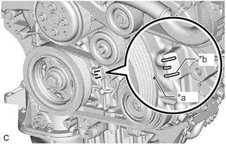
| *a | Timing Mark (Cutout) |
| *b | "0" Timing Mark |
Turn the crankshaft clockwise to align the timing mark (cutout) on the crankshaft pulley with the "0" timing mark on the timing chain cover assembly.
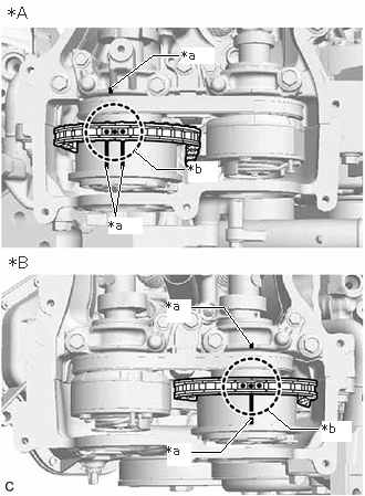
| *A | for Bank 2 |
| *B | for Bank 1 |
| *a | Timing Mark |
| *b | Paint Mark |
Check that the timing marks of the camshaft timing gear assemblies are aligned with the timing marks of the camshaft bearing caps as shown in the illustration.
- HINT:
-
If the marks are not aligned, turn the crankshaft again to align the marks.
Place paint marks on the timing marks and sprockets of each camshaft timing gear assembly and on the links of the chain sub-assembly.
- HINT:
-
Be sure to place the paint marks on 2 links of the chain sub-assembly and on the sprockets of the camshaft timing gear assemblies at the locations of the timing marks of the camshaft timing gear assemblies.
13540
27.REMOVE NO. 1 CHAIN TENSIONER ASSEMBLY
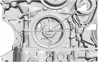
Turn the crankshaft approximately 30° counterclockwise so that there is some slack in the chain sub-assembly.
- HINT:
-
This prevents the valves and pistons from interfering with each other.
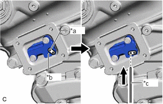
| *a | Lever Hole |
| *b | Tensioner Body |
| *c | Pin |
Align the hole in the lever of the No. 1 chain tensioner assembly with the hole in the tensioner body as shown in the illustration, and then insert a pin with a diameter of 1.0 mm (0.0394 in.) into the hole.
- NOTICE:
-
Check that the pin is locked.
| *a | Timing Mark (Cutout) |
| *b | "0" Timing Mark |
Turn the crankshaft clockwise to align the timing mark (cutout) on the crankshaft pulley with the "0" timing mark on the timing chain cover assembly.
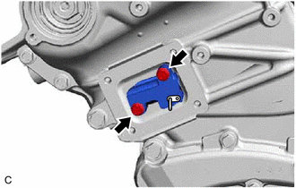
Remove the 2 bolts and No. 1 chain tensioner assembly from the cylinder head sub-assembly.
- NOTICE:
-
Do not drop the No. 1 chain tensioner assembly or bolts into the timing chain cover assembly.
13506
28.DISCONNECT CHAIN SUB-ASSEMBLY (for Bank 1)
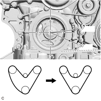
Turn the crankshaft clockwise until it is in the position shown in the illustration so that there is some slack in the chain sub-assembly between the banks.
- CAUTION:
-
As the camshafts may turn suddenly, do not touch the camshafts or camshaft timing gears.
- HINT:
-
When turning the crankshaft, engine oil may spray out of the oil holes.
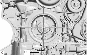
| *a | 5 to 10° |
Turn the crankshaft clockwise until it is in the position shown in the illustration so that the chain sub-assembly can be removed easily.
- HINT:
-
When turning the crankshaft, engine oil may spray out of the oil holes.
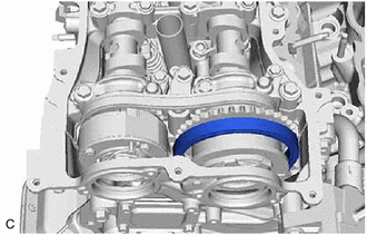
Remove the chain sub-assembly from the sprocket of the camshaft timing gear assembly and set it on the camshaft timing gear assembly.
- CAUTION:
-
As the camshaft may turn suddenly and pinch your fingers when the chain sub-assembly is removed, pinch the chain sub-assembly and lift it upward to remove it from the sprocket.
13550
29.SEPARATE NO. 2 CHAIN TENSIONER ASSEMBLY
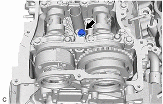
Remove the bolt to separate the No. 2 chain tensioner assembly from the camshaft housing sub-assembly.
30.REMOVE CAMSHAFT TIMING GEAR BOLT (for Intake Side of Bank 1)
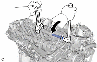
| *a | Hold |

|
Turn |
Use a wrench to hold the hexagonal portion of the camshaft and remove the camshaft timing gear bolt from the camshaft timing gear assembly.
- NOTICE:
- ·
Be careful not to damage the camshaft, camshaft housing sub-assembly or spark plug tube with the wrench.
·If the camshaft timing gear bolt has been struck or dropped, replace it.
31.REMOVE CAMSHAFT TIMING GEAR BOLT (for Exhaust Side of Bank 1)
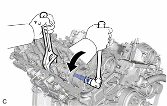
| *a | Hold |
|
|
Turn |
Use a wrench to hold the hexagonal portion of the No. 2 camshaft and remove the camshaft timing gear bolt from the camshaft timing exhaust gear assembly.
- NOTICE:
- ·
Be careful not to damage the No. 2 camshaft, camshaft housing sub-assembly or spark plug tube with the wrench.
·If the camshaft timing gear bolt has been struck or dropped, replace it.
32.REMOVE CAMSHAFT BEARING CAP (for Bank 1)
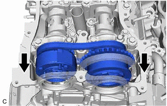
Slide the camshaft timing gear assembly and camshaft timing exhaust gear assembly as shown in the illustration.
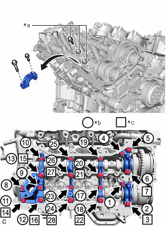
| *a | Replacement Bolt and Washer |
| *b | Part Removal |
| *c | Replacement Bolt and Washer Installation |
Remove the bolts and camshaft bearing caps in the order shown in the illustration. Immediately after removing a camshaft bearing cap, install replacement bolts and washers in the order shown in the illustration.
- Torque:
- 10 N*m (102 kgf*cm, 7 ft.*lbf)
- NOTICE:
- ·
Do not install the camshaft bearing caps when installing replacement bolts and washers.
·Be sure to follow the numerical order when performing this procedure.
·Do not allow replacement bolts or washers to contact the camshaft.
·Do not drop replacement bolts or washers into the cylinder head sub-assembly.
- HINT:
- ·
Arrange the removed parts so that they can be reinstalled in their original locations.
·Part number for replacement bolts: 91551-F0850 (9 bolts)
·Part number for replacement washers: 90201-12028 (18 washers)
13512
33.REMOVE NO. 2 CAMSHAFT
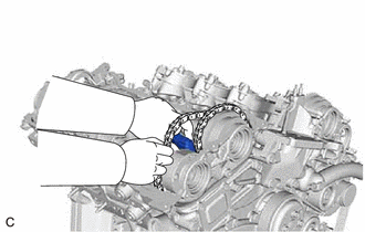
While lifting up the camshaft timing exhaust gear assembly, remove the No. 2 chain tensioner assembly.
Lift up the rear of the No. 2 camshaft so that it is at an angle.
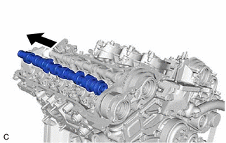
Pull the No. 2 camshaft as shown in the illustration to remove it from the camshaft timing exhaust gear assembly.
13511
34.REMOVE CAMSHAFT
Lift up the rear of the camshaft so that it is at an angle.
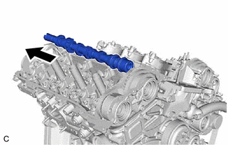
Pull the camshaft as shown in the illustration to remove it from the camshaft timing gear assembly.
13070A
35.REMOVE CAMSHAFT TIMING EXHAUST GEAR ASSEMBLY (for Bank 1)
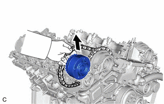
Remove the camshaft timing exhaust gear assembly.
13050
36.REMOVE CAMSHAFT TIMING GEAR ASSEMBLY (for Bank 1)
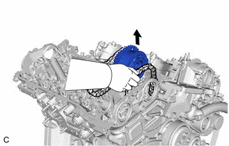
Remove the camshaft timing gear assembly and No. 2 chain sub-assembly.
- NOTICE:
-
Do not drop the chain sub-assembly into the gap between the engine and timing chain cover assembly.
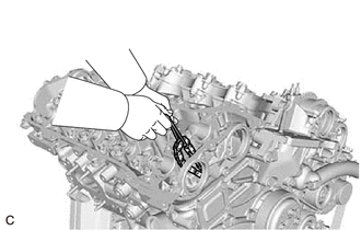
Suspend the chain sub-assembly with a string or equivalent.
13506
37.DISCONNECT CHAIN SUB-ASSEMBLY (for Bank 2)
| *a | Timing Mark (Cutout) |
| *b | "0" Timing Mark |
Turn the crankshaft counterclockwise to align the timing mark (cutout) on the crankshaft pulley with the "0" timing mark on the timing chain cover assembly.
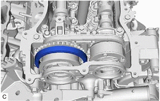
Remove the chain sub-assembly from the sprocket of the camshaft timing gear assembly and set it on the camshaft timing gear assembly.
- CAUTION:
-
As the camshaft may turn suddenly and pinch your fingers when the chain sub-assembly is removed, pinch the chain sub-assembly and lift it upward to remove it from the sprocket.
13560A
38.SEPARATE NO. 3 CHAIN TENSIONER ASSEMBLY
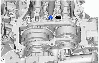
Remove the bolt to separate the No. 3 chain tensioner assembly from the camshaft housing sub-assembly LH.
39.REMOVE CAMSHAFT TIMING GEAR BOLT (for Intake Side of Bank 2)
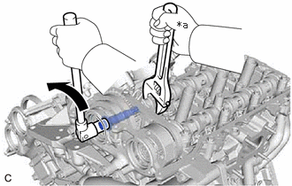
| *a | Hold |
|
|
Turn |
Use a wrench to hold the hexagonal portion of the No. 3 camshaft sub-assembly and remove the camshaft timing gear bolt from the camshaft timing gear assembly.
- NOTICE:
- ·
Be careful not to damage the No. 3 camshaft sub-assembly, camshaft housing sub-assembly LH or spark plug tube with the wrench.
·If the camshaft timing gear bolt has been struck or dropped, replace it.
40.REMOVE CAMSHAFT TIMING GEAR BOLT (for Exhaust Side of Bank 2)
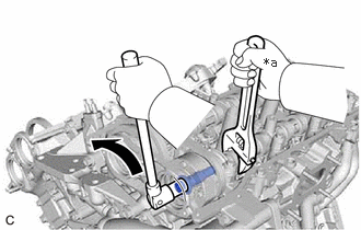
| *a | Hold |
|
|
Turn |
Use a wrench to hold the hexagonal portion of the No. 4 camshaft sub-assembly and remove the camshaft timing gear bolt from the camshaft timing exhaust gear assembly.
- NOTICE:
- ·
Be careful not to damage the No. 4 camshaft sub-assembly, camshaft housing sub-assembly LH or spark plug tube with the wrench.
·If the camshaft timing gear bolt has been struck or dropped, replace it.
41.REMOVE CAMSHAFT BEARING CAP (for Bank 2)
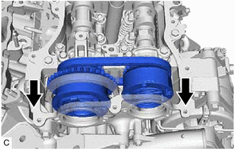
Slide the camshaft timing gear assembly and camshaft timing exhaust gear assembly as shown in the illustration.
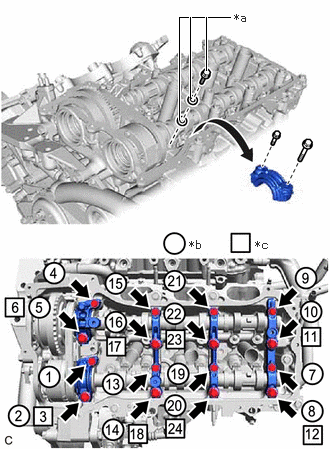
| *a | Replacement Bolt and Washer |
| *b | Part Removal |
| *c | Replacement Bolt and Washer Installation |
Remove the bolts and camshaft bearing caps in the order shown in the illustration. Immediately after removing a camshaft bearing cap, install replacement bolts and washers in the order shown in the illustration.
- Torque:
- 10 N*m (102 kgf*cm, 7 ft.*lbf)
- NOTICE:
- ·
Do not install the camshaft bearing caps when installing replacement bolts and washers.
·Be sure to follow the numerical order when performing this procedure.
·Do not allow replacement bolts or washers to contact the camshaft.
·Do not drop replacement bolts or washers into the cylinder head LH.
- HINT:
- ·
Arrange the removed parts so that they can be reinstalled in their original locations.
·Part number for replacement bolts: 91551-F0850 (8 bolts)
·Part number for replacement washers: 90201-12028 (16 washers)
13054
42.REMOVE NO. 4 CAMSHAFT SUB-ASSEMBLY
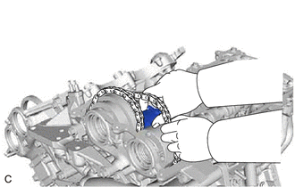
While lifting up the camshaft timing exhaust gear assembly, remove the No. 3 chain tensioner assembly.
Lift up the rear of the No. 4 camshaft sub-assembly so that it is at an angle.
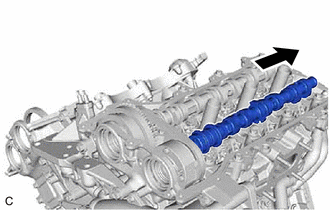
Pull the No. 4 camshaft sub-assembly as shown in the illustration to remove it from the camshaft timing exhaust gear assembly.
13053
43.REMOVE NO. 3 CAMSHAFT SUB-ASSEMBLY
Lift up the rear of the No. 3 camshaft sub-assembly so that it is at an angle.
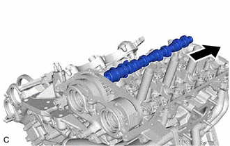
Pull the No. 3 camshaft sub-assembly as shown in the illustration to remove it from the camshaft timing gear assembly.
13070A
44.REMOVE CAMSHAFT TIMING EXHAUST GEAR ASSEMBLY (for Bank 2)
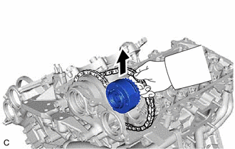
Remove the camshaft timing exhaust gear assembly.
13050
45.REMOVE CAMSHAFT TIMING GEAR ASSEMBLY (for Bank 2)
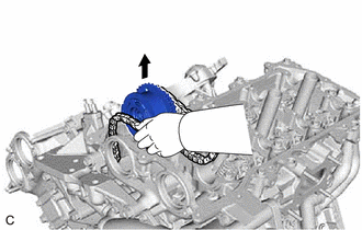
Remove the camshaft timing gear assembly and No. 2 chain sub-assembly.
- NOTICE:
-
Do not drop the chain sub-assembly into the gap between the engine and timing chain cover assembly.
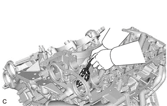
Suspend the chain sub-assembly with a string or equivalent.