HEATING / AIR CONDITIONING VISCOUS HEATER MAGNET CLUTCH(for 1GD-FTV) INSTALLATION
CAUTION / NOTICE / HINT
- NOTICE:
-
Check that coolant (including intercooler coolant) is being sufficiently supplied when starting the engine.
PROCEDURE

 87120G
1.INSTALL VISCOUS HEATER WITH MAGNET CLUTCH ASSEMBLY
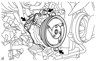
Temporarily install the viscous heater with magnet clutch assembly with the 2 bolts.
Connect the connector.
2.CONNECT HEATER WATER INLET HOSE
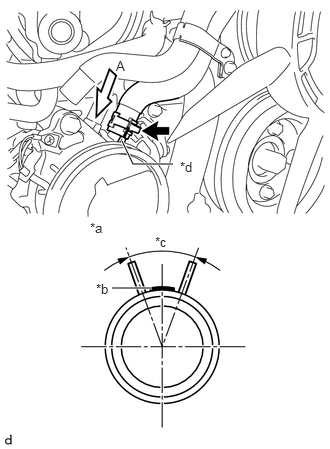
| *a | View A |
| *b | Paint Marking (Red) |
| *c | Clip Installation Angle (40°) |
| *d | Rib |
Align the rib of the viscous heater with magnet clutch assembly with the marking (red). Connect the heater water inlet hose and install the clip within the range shown in the illustration.
- NOTICE:
-
Do not apply excessive force to the heater water inlet hose.
3.CONNECT HEATER WATER OUTLET HOSE
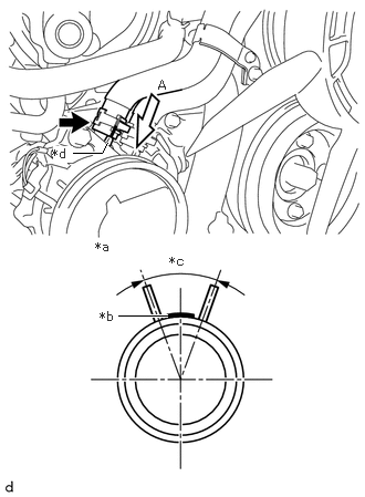
| *a | View A |
| *b | Paint Marking (Red) |
| *c | Clip Installation Angle (40°) |
| *d | Rib |
Align the rib of the viscous heater with magnet clutch assembly with the marking (red). Connect the heater water outlet hose and install the clip within the range shown in the illustration.
- NOTICE:
-
Do not apply excessive force to the heater water outlet hose.
Install the bolt.
- Torque:
- 9.8 N*m (100 kgf*cm, 87 in.*lbf)
16711
4.INSTALL FAN SHROUD
88359
5.INSTALL VISCOUS HEATER V BELT
6.CONNECT OIL COOLER HOSE (for Automatic Transmission)
16470
7.INSTALL RADIATOR RESERVOIR ASSEMBLY
16553B
8.CONNECT NO. 3 SUB RADIATOR HOSE (w/ Urea SCR System)
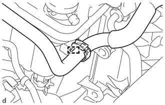
Connect the No. 3 sub radiator hose and attach the clamp.
16640
9.INSTALL INTERCOOLER RESERVOIR ASSEMBLY (w/ Urea SCR System)
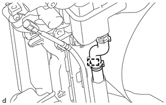
Attach the clamp.
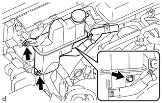
Install the intercooler reservoir assembly with the 3 bolts.
- Torque:
- 5.0 N*m (51 kgf*cm, 44 in.*lbf)
Align to the marking, connect the No. 4 sub radiator hose and install the hose clip in the range shown in the illustration.
- NOTICE:
- ·
Insert the No. 4 sub radiator hose until it contacts the stopper.
·Install by aligning the paint mark on the hose to the paint mark on the pipe.
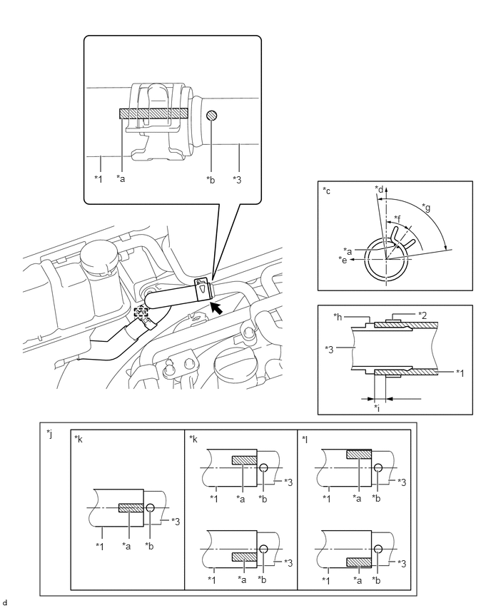
| *1 | No. 4 Sub Radiator Hose | *2 | Hose Clip |
| *3 | Intercooler Cooling Water Pipe | - | - |
| *a | Hose Paint | *b | Pipe Paint |
| *c | Hose Clip Direction | *d | Vehicle Top |
| *e | Vehicle Rear | *f | Hose Clip Installation Range (37°) |
| *g | Hose Clip Clamp Installation Range (90°) | *h | Stopper |
| *i | Hose Clip Installation Range (2 to 5 mm) | *j | No. 4 Sub Radiator Hose Insertion Installation Procedure |
| *k | OK | *l | NG |
Attach the clamp.
161B0
10.INSTALL ELECTRIC WATER PUMP ASSEMBLY (w/ Urea SCR System)
17341K
11.INSTALL INTERCOOLER AIR HOSE (w/o Urea SCR System)
16572D
12.INSTALL NO. 2 RADIATOR HOSE (w/o Urea SCR System)
17342F
13.INSTALL NO. 2 INTERCOOLER AIR HOSE (w/o Urea SCR System)
16571C
14.INSTALL NO. 1 RADIATOR HOSE
82123
15.INSTALL NO. 3 ENGINE WIRE (for Cold Area)
16.ADD ENGINE COOLANT (w/ Urea SCR System)
17.ADD ENGINE COOLANT
51405A
18.INSTALL NO. 1 ENGINE UNDER COVER SUB-ASSEMBLY
52129B
19.INSTALL FRONT BUMPER LOWER COVER
20.CONNECT CABLE TO NEGATIVE BATTERY TERMINAL (for Cold Area)
- NOTICE:
-
When disconnecting the cable, some systems need to be initialized after the cable is reconnected.
-
Click hereGeneral>INTRODUCTION>REPAIR INSTRUCTION>INITIALIZATION
21.INSPECT FOR ENGINE COOLANT LEAK (w/ Urea SCR System)
22.INSPECT FOR COOLANT LEAK
53292A
23.INSTALL UPPER RADIATOR SUPPORT SEAL
12601B
24.INSTALL NO. 1 ENGINE COVER SUB-ASSEMBLY (w/ Urea SCR System)