WINDOW / GLASS WINDSHIELD GLASS INSTALLATION
CAUTION / NOTICE / HINT
- NOTICE:
-
When replacing the windshield glass of a vehicle equipped with a forward recognition camera, make sure to use a Toyota genuine part. If a non-Toyota genuine part is used, the forward recognition camera may not be able to be installed due to a missing bracket. Also, the dynamic radar cruise control system, front camera system, lane departure alert system, road sign assist system, pre-collision system or automatic high beam system may not operate properly due to a difference in the transmissivity or black ceramic border.
PROCEDURE

 75547B
1.INSTALL NO. 3 WINDSHIELD OUTSIDE MOULDING CLIP
- HINT:
-
Perform the following procedures if replacing any No. 3 windshield outside moulding clips.
Install a nose piece to an air riveter or hand riveter.
Insert the mandrel part of a new No. 3 windshield outside moulding clip into the nose piece.
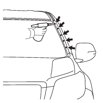
Using the riveter, install the 5 No. 3 windshield outside moulding clips shown in the illustration.
- NOTICE:
-
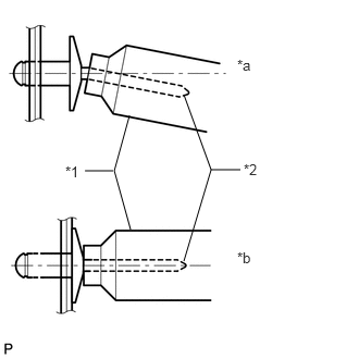 1.24,1.104 1.094,1.635 1.094,1.635 1.25,2.198 false 1.083,1.635 0.813,1.635 false 1.76,0.906 2.021,1.625 2.021,1.625 1.76,2.5 false 2.021,1.625 2.302,1.625 false 2.271,0.542 2.469,0.74 0.198,0.198 10 false *a 2.271,2.385 2.49,2.583 0.219,0.198 10 false *b 0.625,1.563 0.813,1.76 0.188,0.198 10 false *1 2.333,1.542 2.521,1.719 0.188,0.177 10 false *2
*1 Riveter *2 Mandrel *a INCORRECT *b CORRECT
-
Do not pry the No. 3 windshield outside moulding clip with the riveter as this will cause damage to the riveter and mandrel.
- NOTICE:
-
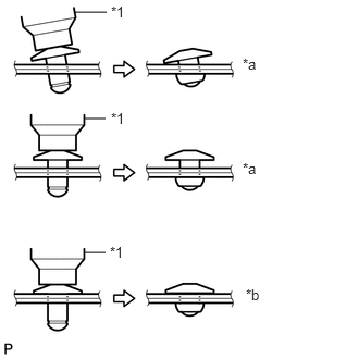 0.719,0.115 1.021,0.115 false 0.813,1.135 1.01,1.135 false 0.813,2.417 1.01,2.417 false 2.323,0.531 2.51,0.708 0.188,0.177 10 false *a 2.323,1.531 2.5,1.708 0.177,0.177 10 false *a 2.354,2.74 2.552,2.917 0.198,0.177 10 false *b 1.052,2.333 1.229,2.49 0.177,0.156 10 false *1 1.063,1.052 1.24,1.208 0.177,0.156 10 false *1 1.063,0.031 1.24,0.188 0.177,0.156 10 false *1
*1 Riveter *a INCORRECT *b CORRECT
- ·
Confirm that the No. 3 windshield outside moulding clips are seated properly against the moulding.
·Do not tilt the riveter when installing the No. 3 windshield outside moulding clip to the moulding.
·Do not leave any space between the No. 3 windshield outside moulding clip head and moulding.
- NOTICE:
-
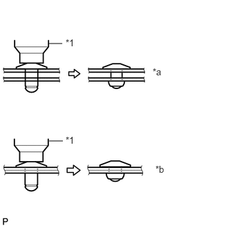 0.74,0.656 0.938,0.656 false 0.74,2.125 0.948,2.125 false 2.302,1 2.5,1.177 0.198,0.177 10 false *a 2.344,2.469 2.552,2.646 0.208,0.177 10 false *b 0.99,0.563 1.188,0.729 0.198,0.167 10 false *1 0.99,2.031 1.198,2.198 0.208,0.167 10 false *1
*1 Riveter *a INCORRECT *b CORRECT
-
Do not leave any space between the moulding and body. Firmly hold together the 2 items while installing the No. 3 windshield outside moulding clip.
- HINT:
-
If the No. 3 windshield outside moulding clip cannot be cut, pull it once and cut it.
75545B
2.INSTALL NO. 1 WINDSHIELD OUTSIDE MOULDING CLIP
Install the 5 No. 1 windshield moulding clips.
- HINT:
-
Use the same procedure to install the 5 No. 1 windshield moulding clips on the other side.
56115A
3.INSTALL NO. 1 WINDSHIELD GLASS STOPPER
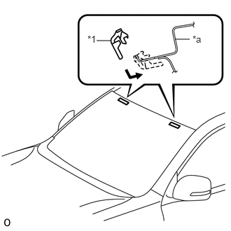
| *1 | No. 1 Windshield Glass Stopper |
| *a | Vehicle Body |
Install 2 new No. 1 windshield glass stoppers to the vehicle body as shown in the illustration.
56116C
4.INSTALL NO. 2 WINDSHIELD GLASS STOPPER
Apply glass primer to the windshield glass where the No. 2 windshield glass stoppers will be installed.
- NOTICE:
- ·
Allow the primer to dry for 3 minutes or more.
·Throw away any leftover primer.
·Do not apply too much primer.
Install 2 new No. 2 windshield glass stoppers to the windshield glass as shown in the illustration.
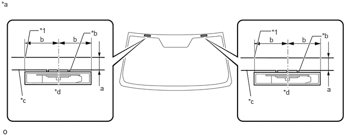
| *1 | Windshield Glass Edge | - | - |
| *a | Backside | *b | Ceramic Notch |
| *c | Ceramic Line | *d | Center |
- Standard:
Area Specified Condition a 14.1 mm (0.555 in.) b 40.0 mm (1.57 in.)
75533G
5.INSTALL WINDSHIELD OUTSIDE MOULDING
Using a brush or sponge, coat the contact surface of the windshield glass and windshield outside moulding with glass primer as shown in the illustration.
- NOTICE:
- ·
Allow the primer coating to dry for 3 minutes or more.
·Do not coat the adhesive with glass primer.
·Throw away any leftover primer.
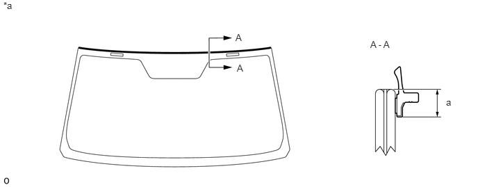
| *a | Backside | - | - |
- Standard:
Area Specified Condition a 7.4 mm (0.291 in.)
Remove the peeling paper from a new windshield outside moulding and install the windshield outside moulding as shown in the illustration.
56117D
6.INSTALL WINDSHIELD GLASS ADHESIVE DAM
Apply glass primer to the windshield glass where the new windshield glass adhesive dam will be installed.
- NOTICE:
- ·
Allow the primer to dry for 3 minutes or more.
·Throw away any leftover primer.
·Do not apply too much primer.
Remove the peeling paper from the adhesive part of the windshield glass adhesive dam. Install the windshield glass adhesive dam (adhesive side) to the windshield glass (glass primer area), but exclude the area above the notches on the upper part of the windshield glass.
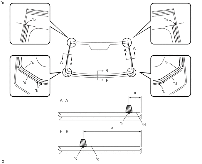
| *a | Backside | *b | Ceramic Notch |
| *c | Dam Center Line | *d | Adhesive Center Line |
- Standard:
Area Specified Condition a 9.5 mm (0.374 in.) b 45.7 mm (1.80 in.)
56111
7.INSTALL WINDSHIELD GLASS
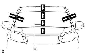
| *a | Matchmarks |
Position the windshield glass.
Using suction cups, place the windshield glass in the correct position.
Check that the entire contact surface of the windshield glass rim is perfectly even.
Place matchmarks on the windshield glass and vehicle body at the locations indicated in the illustration.
- NOTICE:
-
Check that the stoppers are attached to the vehicle body correctly.
- HINT:
- ·
Placing matchmarks is only necessary when installing new windshield glass. When reusing the windshield glass, matchmarks should already be present.
·When reusing the windshield glass, check and correct the matchmark positions.
Using suction cups, remove the windshield glass.
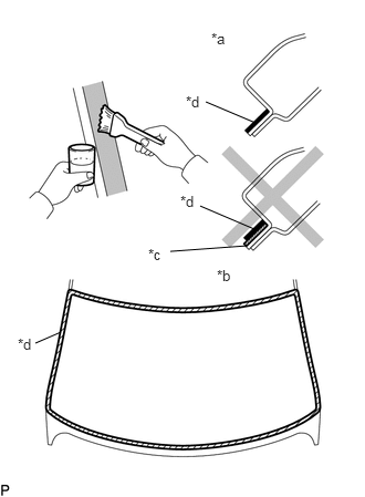
| *a | CORRECT |
| *b | INCORRECT |
| *c | Adhesive |
| *d | Body Primer |
Using a brush, apply body primer to the exposed part of the vehicle body.
- NOTICE:
- ·
Allow the primer to dry for 3 minutes or more.
·Do not apply primer to the adhesive.
·Throw away any leftover primer.
·Do not apply too much primer.
Using a brush or sponge, apply glass primer to the contact surface of the windshield glass.
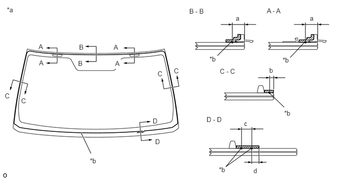
| *a | Backside | *b | Adhesive Center Line |

|
Glass Primer | - | - |
- Standard:
Area Specified Condition a 9.5 mm (0.374 in.) b 3.0 mm (0.118 in.) c 8.0 mm (0.315 in.) d 7.0 mm (0.276 in.)
- NOTICE:
- ·
Allow the primer to dry for 3 minutes or more.
·Throw away any leftover primer.
·Do not apply too much primer.
- HINT:
-
If the primer is applied to an area that is not specified, apply non-residue solvent to a clean cloth and wipe off the excess primer before it dries.
Apply adhesive to the windshield glass.
- Adhesive:
Toyota Genuine Windshield Glass Adhesive or equivalent
Cut off the tip of a cartridge nozzle as shown in the illustration.
- HINT:
-
After cutting off the tip, use all adhesive within the time written in the table below.
- Usage Time Frame:
Temperature Usage Time Frame 35°C (95°F) 15 minutes 20°C (68°F) 1 hour 40 minutes 5°C (41°F) 8 hours
Load a sealer gun with the cartridge.
Apply adhesive to the windshield glass as shown in the illustration.
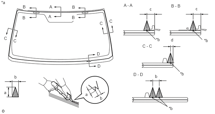
| *a | Backside | *b | Adhesive Center Line |

0,0 0,0
false
|
Adhesive | - | - |
- Standard:
Area Specified Condition a 12.0 mm (0.472 in.) b 8.0 mm (0.315 in.) c 9.5 mm (0.374 in.) d 3.0 mm (0.118 in.)
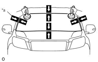
| *a | Matchmarks |
Install the windshield glass to the vehicle body.
Using suction cups, position the windshield glass so that the matchmarks are aligned. Press it in gently along the rim.
Lightly press the outer surface of the windshield glass to ensure that it is securely installed to the vehicle body.
- NOTICE:
- ·
Check that the stoppers are attached to the vehicle body correctly.
·Check that the vehicle body and windshield glass have a small gap between them.
Hold the windshield glass in place securely with protective tape or equivalent until the adhesive hardens.
- NOTICE:
-
Do not drive the vehicle within the time written in the table below.
- Minimum Time:
Temperature Minimum Time Prior to Driving Vehicle 35°C (95°F) 1 hour 30 minutes 20°C (68°F) 5 hours 5°C (41°F) 24 hours
w/ Windshield Deicer System:
Connect the windshield deicer connector.
8.CHECK CHECK FOR LEAK AND REPAIR
Conduct a leak test after the adhesive has completely hardened.
Seal any leaks with auto glass sealer.
63310
9.INSTALL ROOF HEADLINING ASSEMBLY
for 5 Door:
Return the roof headlining to its original position. Refer to the following procedures.
Click hereVehicle Interior>INTERIOR PANELS / TRIM>ROOF HEADLINING (for 5 Door)>INSTALLATION
for 3 Door:
Return the roof headlining to its original position. Refer to the following procedures.
Click hereVehicle Interior>INTERIOR PANELS / TRIM>ROOF HEADLINING (for 3 Door)>INSTALLATION
87810
10.INSTALL INNER REAR VIEW MIRROR ASSEMBLY
89941
11.INSTALL RAIN SENSOR (w/ Rain Sensor)
86401
12.INSTALL FORWARD RECOGNITION WITH HEATER HOOD SUB-ASSEMBLY (w/ Lane Departure Alert System)
8646C
13.INSTALL FORWARD RECOGNITION CAMERA (w/ Lane Departure Alert System)
86464A
14.INSTALL FORWARD RECOGNITION LATCH (w/ Lane Departure Alert System)
86466D
15.INSTALL NO. 1 FORWARD RECOGNITION COVER (w/ Lane Departure Alert System)
86466E
16.INSTALL NO. 2 FORWARD RECOGNITION COVER (w/ Lane Departure Alert System)
81260A
17.INSTALL MAP LIGHT ASSEMBLY
74348
18.INSTALL VISOR HOLDER
74320
19.INSTALL VISOR ASSEMBLY LH
74310
20.INSTALL VISOR ASSEMBLY RH
- HINT:
-
Use the same procedure described for the LH side.
74318
21.INSTALL VISOR BRACKET COVER LH
74317
22.INSTALL VISOR BRACKET COVER RH
- HINT:
-
Use the same procedure described for the LH side.
62212
23.INSTALL FRONT PILLAR GARNISH LH
62211
24.INSTALL FRONT PILLAR GARNISH RH
- HINT:
-
Use the same procedure described for the LH side.
74611F
25.INSTALL NO. 1 ASSIST GRIP
74616C
26.INSTALL FRONT NO. 1 ASSIST GRIP PLUG LH
74615E
27.INSTALL FRONT NO. 1 ASSIST GRIP PLUG RH
- HINT:
-
Use the same procedure described for the LH side.
62312B
28.INSTALL FRONT DOOR OPENING TRIM WEATHERSTRIP LH
62311B
29.INSTALL FRONT DOOR OPENING TRIM WEATHERSTRIP RH
- HINT:
-
Use the same procedure described for the LH side.
62112
30.INSTALL COWL SIDE TRIM BOARD LH
62111C
31.INSTALL COWL SIDE TRIM BOARD RH
- HINT:
-
Use the same procedure described for the LH side.
67920
32.INSTALL DOOR SCUFF PLATE ASSEMBLY LH
67910
33.INSTALL DOOR SCUFF PLATE ASSEMBLY RH
- HINT:
-
Use the same procedure described for the LH side.
75536B
34.INSTALL WINDSHIELD LOWER OUTSIDE MOULDING LH
Attach the 5 clips to install a new moulding.
Remove the protective tape from the edges of the moulding.
75535A
35.INSTALL WINDSHIELD LOWER OUTSIDE MOULDING RH
- HINT:
-
Use the same procedure described for the LH side.
55781E
36.INSTALL COWL TOP VENTILATOR LOUVER SUB-ASSEMBLY
37.INSTALL FRONT WIPER ARM AND BLADE ASSEMBLY RH
38.INSTALL FRONT WIPER ARM AND BLADE ASSEMBLY LH
85192
39.INSTALL WINDSHIELD WIPER ARM COVER
53867H
40.INSTALL FRONT FENDER TO COWL SIDE SEAL LH
53866J
41.INSTALL FRONT FENDER TO COWL SIDE SEAL RH
- HINT:
-
Use the same procedure for the LH side.
53828J
42.INSTALL FRONT FENDER SIDE PANEL PROTECTOR LH
53827K
43.INSTALL FRONT FENDER SIDE PANEL PROTECTOR RH
- HINT:
-
Use the same procedure for the LH side.
53292A
44.INSTALL UPPER RADIATOR SUPPORT SEAL
45.CONNECT CABLE TO NEGATIVE BATTERY TERMINAL
46. INITIALIZATION AFTER RECONNECTING BATTERY TERMINAL
Click hereGeneral>SETUP>WHEN DISCONNECTING OR RECONNECTING BATTERY TERMINAL>WORK PROCEDURE
- HINT:
-
When disconnecting and reconnecting the battery, there is an automatic learning function that completes learning when the respective system is used.
-
Click hereGeneral>SETUP>WHEN DISCONNECTING OR RECONNECTING BATTERY TERMINAL>AUTOMATIC LEARNING CHART
8646C
47.ADJUST FORWARD RECOGNITION CAMERA
One time Recognition:
Click hereEngine / Hybrid System>CRUISE CONTROL>FRONT CAMERA>ADJUSTMENT (ONE TIME RECOGNITION)
Sequential Recognition:
Click hereEngine / Hybrid System>CRUISE CONTROL>FRONT CAMERA>ADJUSTMENT (SEQUENTIAL RECOGNITION)