1GD-FTV COOLING RADIATOR INSTALLATION
PROCEDURE

 12209F
1.INSTALL OIL RETURN PIPE SUB-ASSEMBLY (w/o Urea SCR System)
Attach the 2 clamps to install the oil return pipe sub-assembly to the radiator assembly.
17940D
2.INSTALL INTERCOOLER ASSEMBLY (w/o Urea SCR System)
16550
3.INSTALL INTERCOOLER COOLING RADIATOR ASSEMBLY (w/ Urea SCR System)
16562
4.INSTALL NO. 2 RADIATOR TO SUPPORT SEAL
16593
5.INSTALL NO. 1 RADIATOR AIR GUIDE
Install the No. 1 radiator air guide with the 2 bolts.
- Torque:
- 11 N*m (112 kgf*cm, 8 ft.*lbf)
16563
6.INSTALL NO. 3 RADIATOR TO SUPPORT SEAL
Install a new No. 3 radiator to support seal to the No. 1 radiator guide.
16400
7.INSTALL RADIATOR ASSEMBLY
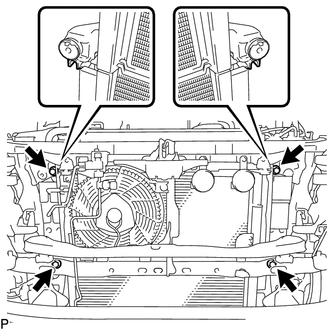
Insert the tabs of the radiator collar into the radiator service holes.
Install the radiator assembly with the 4 bolts.
- Torque:
- 18 N*m (184 kgf*cm, 13 ft.*lbf)
53294C
8.INSTALL RADIATOR SIDE DEFLECTOR LH
Attach the 3 claws to install the radiator side deflector LH, and install the clip.
53293C
9.INSTALL RADIATOR SIDE DEFLECTOR RH
Attach the 3 claws to install the radiator side deflector RH, and install the clip.
52521
10.INSTALL FRONT BUMPER CENTER UPPER RETAINER
52119A
11.INSTALL FRONT BUMPER COVER
52129B
12.INSTALL FRONT BUMPER LOWER COVER
16711
13.INSTALL FAN SHROUD
Install the fan pulley.
Place the fan shroud together with the fan with fluid coupling assembly between the engine and radiator assembly.
- NOTICE:
-
Be careful not to damage the radiator core.
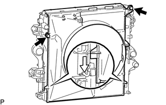
w/o Urea SCR System:
Attach the 2 guides and install the fan shroud with the 2 bolts.
- Torque:
- 5.0 N*m (51 kgf*cm, 44 in.*lbf)
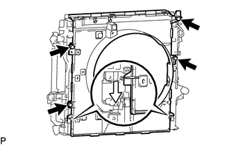
w/ Urea SCR System:
Attach the 2 guides and install the fan shroud with the 4 bolts.
- Torque:
- 5.0 N*m (51 kgf*cm, 44 in.*lbf)
Temporarily install the fan with fluid coupling assembly to the engine water pump assembly with the 4 nuts.
- NOTICE:
- ·
Make sure to match the paint mark colors on the fan with fluid coupling assembly with the stud bolts of the same color on the engine water pump assembly.
·When installing the fan and generator V belt, make sure to securely tighten the nuts of the fan with fluid coupling assembly so that the fan pulley is properly aligned.
Install the fan and generator V belt.
Click hereEngine / Hybrid System>1GD-FTV (ENGINE MECHANICAL)>DRIVE BELT>INSTALLATION
Tighten the 4 nuts holding the fan with fluid coupling assembly.
- Torque:
- 23 N*m (235 kgf*cm, 17 ft.*lbf)
88359
14.INSTALL VISCOUS HEATER V BELT (w/ Viscous Heater)
15.CONNECT OIL COOLER HOSE (for Automatic Transmission)
Connect the oil cooler hose to the radiator assembly and slide the 2 hose clamps to secure the hose.
Attach the 2 clamps and connect the oil cooler hose to the fan shroud with the bolt.
- Torque:
- 5.5 N*m (56 kgf*cm, 49 in.*lbf)
16470
16.INSTALL RADIATOR RESERVOIR ASSEMBLY
Install the radiator reservoir assembly with the 3 bolts.
- Torque:
- 5.0 N*m (51 kgf*cm, 44 in.*lbf)
Attach the 2 clamps to connect the No. 1 water by-pass hose to the fan shroud.
Connect the No. 1 water by-pass hose to the radiator assembly and slide the hose clamp to secure the hose.
Connect the No. 2 water by-pass hose to the water inlet and slide the hose clamp to secure the hose.
Attach the 2 clamps to connect the No. 2 water by-pass hose to the fan shroud.
16640
17.INSTALL INTERCOOLER RESERVOIR ASSEMBLY (w/ Urea SCR System)
Install the intercooler reservoir assembly with the 3 bolts.
- Torque:
- 5.0 N*m (51 kgf*cm, 44 in.*lbf)
16554B
18.INSTALL NO. 4 SUB-RADIATOR HOSE (w/ Urea SCR System)
Connect the No. 4 sub-radiator hose to the intercooler reservoir assembly and intercooler cooling water pipe, and slide the 2 hose clamps to secure the hose.
Attach the clamp.
16553B
19.INSTALL NO. 3 SUB-RADIATOR HOSE (w/ Urea SCR System)
Connect the No. 3 sub-radiator hose to the intercooler cooling radiator assembly and intercooler cooling water pipe, and slide the 2 hose clamps to secure the hose.
Attach the clamp.
161B0
20.INSTALL ELECTRIC WATER PUMP ASSEMBLY (w/ Urea SCR System)
Install the electric water pump assembly to the fan shroud with the 2 bolts.
- Torque:
- 7.0 N*m (71 kgf*cm, 62 in.*lbf)
Connect the connector and attach the 4 wire harness clamps, to the electric water pump assembly and fan shroud.
16551B
21.INSTALL NO. 1 SUB-RADIATOR HOSE (w/ Urea SCR System)
Connect the No. 1 sub-radiator hose to the intercooler reservoir assembly and electric water pump assembly, and slide the 2 hose clamps to secure the hose.
Attach the clamp.
16552B
22.INSTALL NO. 2 SUB-RADIATOR HOSE (w/ Urea SCR System)
Connect the No. 2 sub-radiator hose to the intercooler cooling radiator assembly and electric water pump assembly, and slide the 2 hose clamps to secure the hose.
17341K
23.INSTALL INTERCOOLER AIR HOSE (w/o Urea SCR System)
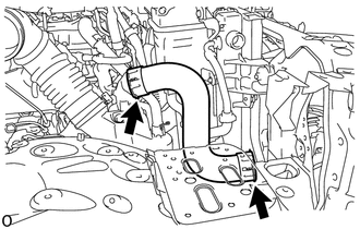
Install the intercooler air hose to the intercooler assembly and compressor outlet elbow and lock the retainers.
- NOTICE:
-
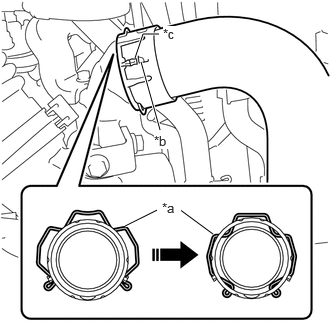 1.667,1.354 1.469,0.646 true 1.406,0.604 1.49,0.354 1.49,0.354 1.656,0.354 true 1.302,2.354 1.635,2.188 true 2.219,2.438 1.865,2.177 true 1.688,2.083 1.885,2.25 0.198,0.167 10 true *a 1.698,0.271 1.917,0.438 0.219,0.167 10 true *c 1.604,1.385 1.802,1.552 0.198,0.167 10 true *b
*a Retainer *b Protrusion *c Stopper
-
Securely insert the retainer so that the 4 locks are engaged. Then, pull and check that the locks are engaged and that the hose cannot be pulled out.
- HINT:
-
Install so that the protrusion on the air intake connector and the stoppers are aligned.
17342F
24.INSTALL NO. 2 INTERCOOLER AIR HOSE (w/o Urea SCR System)
16572D
25.INSTALL NO. 2 RADIATOR HOSE
Install the No. 2 radiator hose and slide the 2 hose clamps to secure the hose.
16571C
26.INSTALL NO. 1 RADIATOR HOSE
Install the No. 1 radiator hose and slide the 2 hose clamps to secure the hose.
82123
27.INSTALL NO. 3 ENGINE WIRE (for Cold Area Specification Vehicles)
Attach the 3 wire harness clamps to connect the No. 3 engine wire to the fan shroud.
Connect the 2 cables to the positive battery terminals.
28.CONNECT CABLE TO NEGATIVE BATTERY TERMINAL (for Cold Area Specification Vehicles)
Click hereGeneral>SETUP>WHEN DISCONNECTING OR RECONNECTING BATTERY TERMINAL>WORK PROCEDURE
- HINT:
-
When disconnecting and reconnecting the battery, there is an automatic learning function that completes learning when the respective system is used.
-
Click hereGeneral>SETUP>WHEN DISCONNECTING OR RECONNECTING BATTERY TERMINAL>AUTOMATIC LEARNING CHART
29.ADD ENGINE COOLANT (w/ Urea SCR System)
30.ADD ENGINE COOLANT
31.INSPECT FOR ENGINE COOLANT LEAK (w/ Urea SCR System)
32.INSPECT FOR ENGINE COOLANT LEAK
51405A
33.INSTALL NO. 1 ENGINE UNDER COVER SUB-ASSEMBLY
53292A
34.INSTALL UPPER RADIATOR SUPPORT SEAL
Install the upper radiator support seal with the 13 clips.