SUSPENSION CONTROL STABILIZER CONTROL TUBE(w/ KDSS) INSTALLATION
PROCEDURE

 48890
1.INSTALL FRONT NO. 1 STABILIZER CONTROL TUBE ASSEMBLY
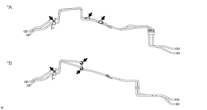
| *A | for 1GR-FE | *B | for 1GD-FTV |
Using a union nut wrench, disconnect the 2 flare nuts of a new front No. 1 stabilizer control tube assembly.
Remove the bolt and clamp from the front No. 1 stabilizer control tube assembly.
Disassemble the front No. 1 stabilizer control tube assembly.
Pull the front No. 1 stabilizer control tube assembly (upper part) and front No. 1 stabilizer control tube assembly (lower part) through the vehicle.
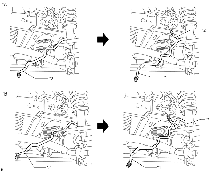
| *A | for 1GR-FE | *B | for 1GD-FTV |
| *1 | Front No. 1 Stabilizer Control Tube Assembly (Upper Part) | *2 | Front No. 1 Stabilizer Control Tube Assembly (Lower Part) |
Temporarily install the 2 flare nuts on the front No. 1 stabilizer control tube assembly (front stabilizer with tube cylinder assembly side).
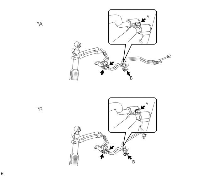
| *A | for 1GR-FE | *B | for 1GD-FTV |
Install the clamp to the front No. 1 stabilizer control tube assembly with the bolt (labeled A).
Connect the clamp to the body with the bolt (labeled B).
- Torque:
- 29 N*m (296 kgf*cm, 21 ft.*lbf)
Temporarily install the 4 flare nuts on the disconnected end of the front No. 1 stabilizer control tube assembly (stabilizer control with accumulator housing side).
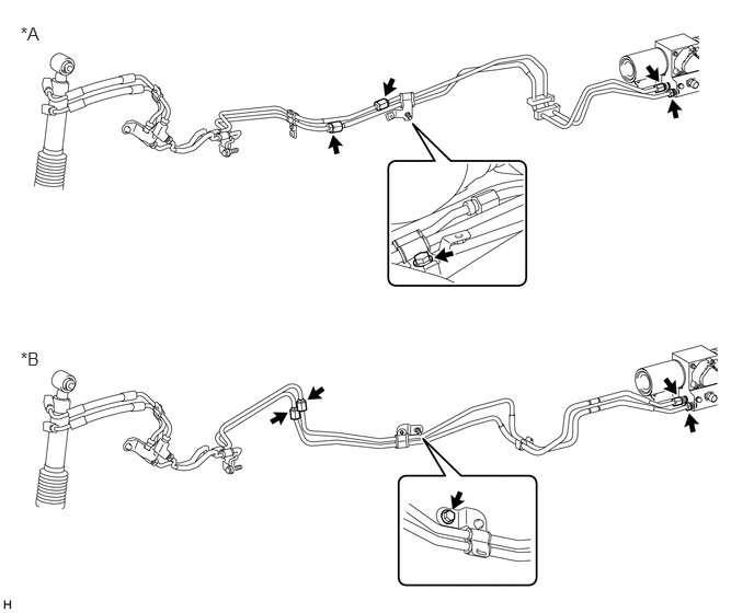
| *A | for 1GR-FE | *B | for 1GD-FTV |
Connect the clamp to the body with the bolt.
for 1GR-FE:
Tighten the 6 flare nuts on the front No. 1 stabilizer control tube assembly.
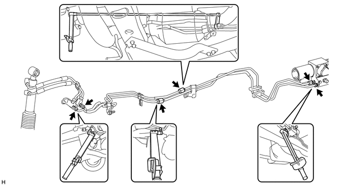
- Torque:
- 44 N*m (450 kgf*cm, 33 ft.*lbf)
- NOTICE:
-
Use the formula to calculate special torque values for situations where a union nut wrench is combined with a torque wrench (See page General>INTRODUCTION>REPAIR INSTRUCTION>PRECAUTION).
for 1GD-FTV:
Tighten the 6 flare nuts on the front No. 1 stabilizer control tube assembly.
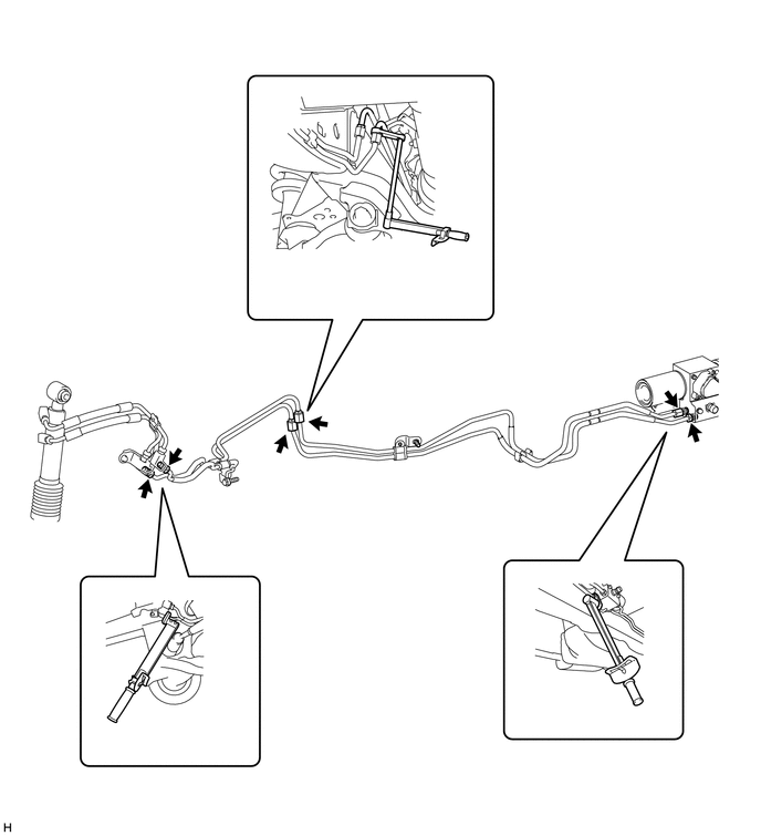
- Torque:
- 44 N*m (450 kgf*cm, 33 ft.*lbf)
- NOTICE:
-
Use the formula to calculate special torque values for situations where a union nut wrench is combined with a torque wrench (See page ).
48827D
2.INSTALL FRONT STABILIZER TUBE PROTECTOR (for 1GR-FE)
Install the front stabilizer tube protector with the 2 bolts.
- Torque:
- 29 N*m (296 kgf*cm, 21 ft.*lbf)
48880
3.INSTALL REAR NO. 1 STABILIZER CONTROL TUBE ASSEMBLY
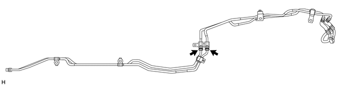
Disconnect the 2 flare nuts of a new rear No. 1 stabilizer control tube assembly.
Move the rear No. 1 stabilizer control tube assembly (rear stabilizer control cylinder side) towards the outside of the frame.
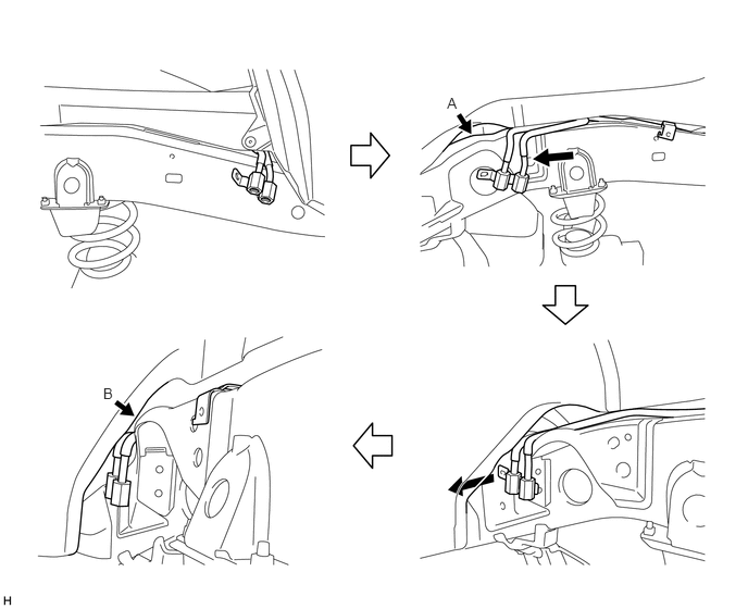
Using a plastic-faced hammer, lightly tap the rear No. 1 stabilizer control tube assembly (rear stabilizer control cylinder side) and slide it to the left.
- NOTICE:
- ·
Make sure that the rear No. 1 stabilizer control tube assembly is not deformed, as the gaps shown by arrows A and B in the illustration are small.
·Slide the rear No. 1 stabilizer control tube assembly to the left so that the flare nut part is between the frame and wheel house.
·If the flare nut part protrudes on the wheel house side, move the part back to the rear of the vehicle and slide it once again to install it.
Temporarily install the 4 flare nuts on the disconnected end of the rear No. 1 stabilizer control tube assembly (stabilizer control with accumulator housing side).
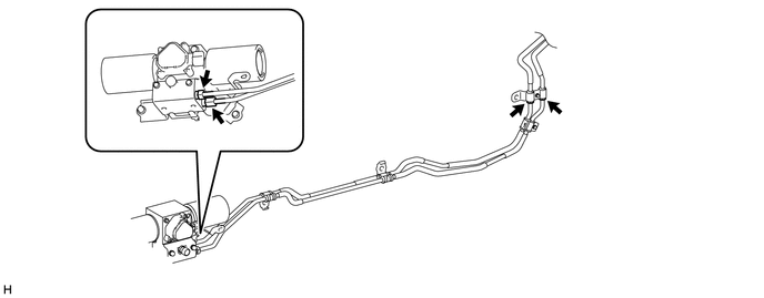
Install the rear No. 1 stabilizer control tube assembly with the 5 bolts.
- Torque:
- 29 N*m (296 kgf*cm, 21 ft.*lbf)
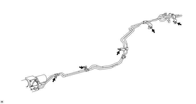
Tighten the 4 flare nuts on the rear No. 1 stabilizer control tube assembly.
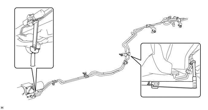
- Torque:
- 44 N*m (450 kgf*cm, 33 ft.*lbf)
- NOTICE:
-
Use the formula to calculate special torque values for situations where a union nut wrench is combined with a torque wrench (See page General>INTRODUCTION>REPAIR INSTRUCTION>PRECAUTION).
Install the rear stabilizer control tubes to the rear stabilizer control cylinder with the 2 union bolts and 2 new pressure port gaskets.
- Torque:
- 48 N*m (484 kgf*cm, 35 ft.*lbf)
- NOTICE:
-
Insert the stoppers of the rear stabilizer control tubes into the rear stabilizer control cylinder.
48540
4.INSTALL REAR SHOCK ABSORBER ASSEMBLY LH
89570A
5.INSTALL FUEL PUMP CONTROL ECU ASSEMBLY
6.BLEED AIR FROM SUSPENSION FLUID
7.APPLY PRESSURE ACCORDING TO TEMPERATURE MANAGEMENT CHART WHEN FILLING FLUID
8.INSPECT FOR SUSPENSION FLUID LEAK
9.INSTALL FRONT WHEEL
- Torque:
- 112 N*m (1142 kgf*cm, 83 ft.*lbf)
10.INSTALL REAR WHEEL
- Torque:
- 112 N*m (1142 kgf*cm, 83 ft.*lbf)
11.INSTALL SPARE TIRE
12.MEASURE VEHICLE HEIGHT
51495
13.INSTALL TRANSMISSION UNDER COVER
51405A
14.INSTALL NO. 1 ENGINE UNDER COVER SUB-ASSEMBLY
52129B
15.INSTALL FRONT BUMPER COVER LOWER
896B1
16.INSTALL UREA PUMP CONTROL ECU (for 1GD-FTV)
48826D
17.INSTALL STABILIZER CONTROL VALVE PROTECTOR
Install the stabilizer control valve protector with the 2 bolts.
- Torque:
- 29 N*m (296 kgf*cm, 21 ft.*lbf)
18.INSTALL SIDE STEP ASSEMBLY LH
19.CONNECT CABLE TO NEGATIVE BATTERY TERMINAL
20. INITIALIZATION AFTER RECONNECTING BATTERY TERMINAL
Click hereGeneral>SETUP>WHEN DISCONNECTING OR RECONNECTING BATTERY TERMINAL>WORK PROCEDURE
- HINT:
-
When disconnecting and reconnecting the battery, there is an automatic learning function that completes learning when the respective system is used.
-
Click hereGeneral>SETUP>WHEN DISCONNECTING OR RECONNECTING BATTERY TERMINAL>AUTOMATIC LEARNING CHART