1UR-FE ENGINE MECHANICAL ENGINE UNIT INSTALLATION
PROCEDURE

 86011Q
1.INSTALL NOISE FILTER
for Bank 2:
Install the noise filter to the cylinder head cover with the bolt.
- Torque:
- 10 N*m (102 kgf*cm, 7 ft.*lbf)
for Bank 1:
Install the noise filter to the cylinder head cover with the bolt.
- Torque:
- 10 N*m (102 kgf*cm, 7 ft.*lbf)
19500
2.INSTALL IGNITION COIL ASSEMBLY
Install the 8 ignition coils with the 8 bolts.
- Torque:
- 10 N*m (102 kgf*cm, 7 ft.*lbf)
16294
3.INSTALL NO. 11 WATER BY-PASS HOSE
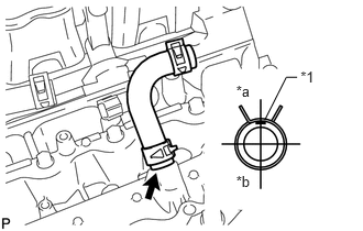
Install the No. 11 water by-pass hose.
| *1 | Paint Mark |
| *a | Rear |
| *b | Front |
- HINT:
- ·
When connecting the hose, make sure the paint marks and clips are as shown in the illustration.
·The direction of the hose clamp is indicated in the illustration.
82121
4.INSTALL ENGINE WIRE
Attach the 3 wire harness clamps to install the engine wire.
Connect the 4 knock sensor connectors.
Install the bolt.
- Torque:
- 8.0 N*m (82 kgf*cm, 71 in.*lbf)
12611
5.INSTALL NO. 1 ENGINE COVER
12612A
6.INSTALL NO. 2 ENGINE COVER
12215
7.INSTALL SEPARATOR CASE
16603
8.INSTALL NO. 1 IDLER PULLEY SUB-ASSEMBLY
16173
9.INSTALL WATER PUMP PULLEY
16261G
10.INSTALL NO. 1 WATER BY-PASS HOSE
16268L
11.INSTALL NO. 2 WATER BY-PASS PIPE SUB-ASSEMBLY
12613
12.INSTALL NO. 3 ENGINE COVER
12614
13.INSTALL NO. 4 ENGINE COVER
23808
14.INSTALL NO. 2 FUEL DELIVERY PIPE SUB-ASSEMBLY
23807
15.INSTALL FUEL DELIVERY PIPE SUB-ASSEMBLY
12315
16.INSTALL FRONT NO. 1 ENGINE MOUNTING BRACKET LH
Install the front No. 1 engine mounting bracket LH with the 4 bolts.
- Torque:
- 35 N*m (357 kgf*cm, 26 ft.*lbf)
12311
17.INSTALL FRONT NO. 1 ENGINE MOUNTING BRACKET RH
Install the front No. 1 engine mounting bracket RH with the 4 bolts.
- Torque:
- 35 N*m (357 kgf*cm, 26 ft.*lbf)
25635A
18.INSTALL NO. 1 EGR PIPE BRACKET
Install the No. 1 EGR pipe bracket with the 3 bolts.
- Torque:
- 21 N*m (214 kgf*cm, 15 ft.*lbf)
16332
19.INSTALL NO. 1 WATER OUTLET PIPE
Install the No. 1 water outlet pipe with the 2 bolts.
- Torque:
- 10 N*m (102 kgf*cm, 7 ft.*lbf)
16294
20.CONNECT NO. 11 WATER BY-PASS HOSE
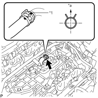
Connect the No. 11 water by-pass hose.
| *1 | Paint Mark |
| *a | Upper Side |
- HINT:
-
The direction of the hose clamp is indicated in the illustration.
16296
21.INSTALL NO. 8 WATER BY-PASS HOSE
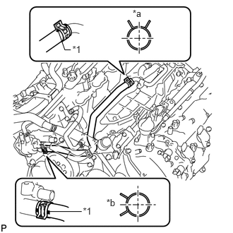
Install the No. 8 water by-pass hose.
| *1 | Paint Mark |
| *a | Upper Side |
| *b | Front |
- HINT:
- ·
When connecting the hose, make sure the paint marks and clips are as shown in the illustration.
·The direction of each hose clamp is indicated in the illustration.
16278K
22.INSTALL NO. 2 WATER BY-PASS PIPE
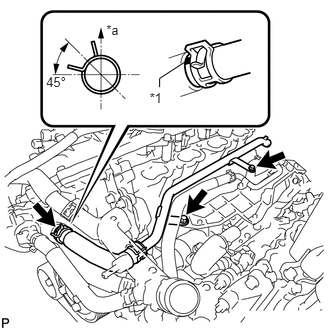
Install the No. 2 water by-pass pipe with the 2 bolts and connect the hose.
- Torque:
- 10 N*m (102 kgf*cm, 7 ft.*lbf)
| *1 | Paint Mark |
| *a | Upper Side |
- HINT:
- ·
When connecting the hose, make sure the paint marks and clips are as shown in the illustration.
·The direction of each hose clamp is indicated in the illustration.
17363Q
23.INSTALL NO. 3 AIR TUBE (w/ Secondary Air Injection System)
Install the No. 3 air tube with the bolt.
- Torque:
- 10 N*m (102 kgf*cm, 7 ft.*lbf)
17364A
24.INSTALL NO. 4 AIR TUBE (w/ Secondary Air Injection System)
Install the No. 4 air tube with the bolt.
- Torque:
- 10 N*m (102 kgf*cm, 7 ft.*lbf)
25710
25.INSTALL AIR SWITCHING VALVE ASSEMBLY (for Bank 2)
23902
26.INSTALL FUEL TUBE SUB-ASSEMBLY
27.INSTALL FUEL HOSE
28.INSTALL ENGINE WIRE