1UR-FE COOLING WATER PUMP INSTALLATION
PROCEDURE

 16100
1.INSTALL ENGINE WATER PUMP ASSEMBLY
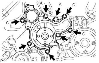
Install a new gasket and the engine water pump with the 8 bolts shown in the illustration.
- Torque:
- for bolt A : 47 N*m (479 kgf*cm, 35 ft.*lbf)
- for bolt B : 23 N*m (235 kgf*cm, 17 ft.*lbf)
- for bolt C : 20 N*m (204 kgf*cm, 15 ft.*lbf)
- Standard Bolt:
Item Length Thread Diameter Bolt A 80 mm (3.15 in.) 10 mm (0.394 in.) Bolt B 70 mm (2.76 in.) 8 mm (0.315 in.) Bolt C 25 mm (0.984 in.) 8 mm (0.315 in.)
16173
2.INSTALL WATER PUMP PULLEY
Temporarily install the water pump pulley with the 4 bolts.
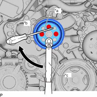
| *a | Protective Tape |
| *b | Hold |
| *c | Turn |
Using a screwdriver or equivalent with its tip wrapped in protective tape, hold the water pump pulley and tighten the 4 bolts.
- Torque:
- 21 N*m (214 kgf*cm, 15 ft.*lbf)
16323
3.INSTALL WATER INLET HOUSING
Install a new gasket to the engine water pump.
Install the water inlet housing with the 3 bolts.
- Torque:
- 21 N*m (214 kgf*cm, 15 ft.*lbf)
16281F
4.CONNECT NO. 5 WATER BY-PASS HOSE
16268L
5.INSTALL NO. 2 WATER BY-PASS PIPE SUB-ASSEMBLY
Connect the 4 hoses.
Install the water by-pass pipe with the 2 bolts.
- Torque:
- 10 N*m (102 kgf*cm, 7 ft.*lbf)
16261G
6.INSTALL NO. 1 WATER BY-PASS HOSE
16261L
7.CONNECT WATER BY-PASS HOSE
8.INSTALL AIR TUBE SUB-ASSEMBLY (w/ Secondary Air Injection System)
16572D
9.INSTALL NO. 2 RADIATOR HOSE
16711
10.INSTALL FAN SHROUD
16571C
11.INSTALL NO. 1 RADIATOR HOSE
12.INSTALL AIR CLEANER CAP AND HOSE
11209
13.INSTALL V-BANK COVER SUB-ASSEMBLY
14.ADD ENGINE COOLANT
15.INSPECT FOR COOLANT LEAK
51405C
16.INSTALL NO. 1 ENGINE UNDER COVER SUB-ASSEMBLY
53806
17.INSTALL FRONT FENDER SPLASH SHIELD SUB-ASSEMBLY LH
53805
18.INSTALL FRONT FENDER SPLASH SHIELD SUB-ASSEMBLY RH
19.INSTALL COOLER COMPRESSOR ASSEMBLY