1UR-FE FUEL FUEL INJECTOR INSTALLATION
PROCEDURE

 23250
1.INSTALL FUEL INJECTOR ASSEMBLY
Attach the 3 clamps to install the No. 6 wire harness to the fuel delivery pipe.
Attach the 3 clamps to install the No. 7 wire harness to the No. 2 fuel delivery pipe.
Apply gasoline or spindle oil to a new O-ring and install the O-ring to the injector.
- NOTICE:
-
Make sure that there is no damage or foreign material in the groove of the injector when installing the O-ring.
Connect the injector connector.
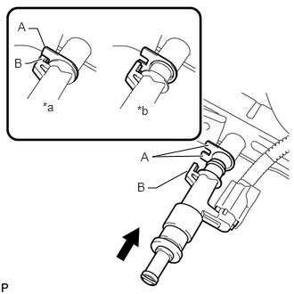
Install the injector to the delivery pipe as shown in the illustration.
| *a | CORRECT |
| *b | INCORRECT |
- NOTICE:
- ·
Make sure that there are no scratches or foreign matter in or around the insertion hole of the delivery pipe.
·When inserting the injector, be careful not to damage the O-ring.
·Attach the part of the injector labeled B between the parts of the delivery pipe labeled A.
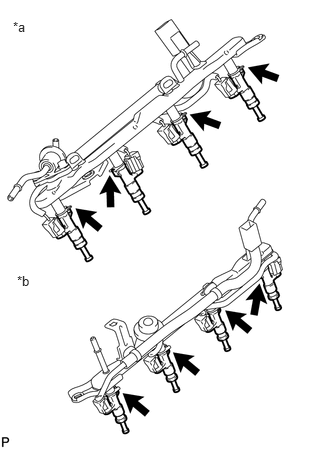
Check that each injector is installed to the delivery pipe facing the direction shown in the illustration.
| *a | Fuel Delivery Pipe |
| *b | No. 2 Fuel Delivery Pipe |
23808
2.INSTALL NO. 2 FUEL DELIVERY PIPE SUB-ASSEMBLY
Install the 2 delivery pipe spacers and 4 insulators to the cylinder head LH.
Install the delivery pipe together with the injectors to the cylinder head LH.
Install the 2 bolts.
- Torque:
- 21 N*m (214 kgf*cm, 15 ft.*lbf)
- NOTICE:
-
 1.073,0.104 1.219,0.104 1.219,0.104 1.406,0.865 true 0.438,0.635 0.604,0.635 0.604,0.635 0.958,0.885 false 0.448,1.052 0.927,1.052 false 0.667,1.396 0.979,1.396 true 0.906,1.688 1.104,1.833 0.198,0.146 10 false *a 1.99,1.677 2.188,1.833 0.198,0.156 10 false *b 0.448,1.302 0.625,1.479 0.177,0.177 10 false *2 0.885,0.01 1.052,0.198 0.167,0.188 10 false *1 0.188,0.552 0.313,0.698 0.125,0.146 10 false A 0.198,0.969 0.323,1.115 0.125,0.146 10 false B
-
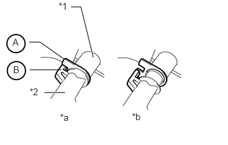
Make sure that the part of the injector labeled B is between the parts of the delivery pipe labeled A.
| *1 | Fuel Delivery Pipe |
| *2 | Fuel Injector |
| *a | CORRECT |
| *b | INCORRECT |
Connect the No. 7 wire harness connector.
23807
3.INSTALL FUEL DELIVERY PIPE SUB-ASSEMBLY
Install the 2 delivery pipe spacers and 4 insulators to the cylinder head RH.
Install the delivery pipe together with the injectors to the cylinder head RH.
Install the 2 bolts.
- Torque:
- 21 N*m (214 kgf*cm, 15 ft.*lbf)
- NOTICE:
-
1.073,0.104 1.219,0.104 1.219,0.104 1.406,0.865 true 0.438,0.635 0.604,0.635 0.604,0.635 0.958,0.885 false 0.448,1.052 0.927,1.052 false 0.667,1.396 0.979,1.396 true 0.906,1.688 1.104,1.833 0.198,0.146 10 false *a 1.99,1.677 2.188,1.833 0.198,0.156 10 false *b 0.448,1.302 0.625,1.479 0.177,0.177 10 false *2 0.885,0.01 1.052,0.198 0.167,0.188 10 false *1 0.188,0.552 0.313,0.698 0.125,0.146 10 false A 0.198,0.969 0.323,1.115 0.125,0.146 10 false B
-
Make sure that the part of the injector labeled B is between the parts of the delivery pipe labeled A.
| *1 | Fuel Delivery Pipe |
| *2 | Fuel Injector |
| *a | CORRECT |
| *b | INCORRECT |
Connect the No. 6 wire harness connector.
23271F
4.CONNECT FUEL HOSE
Connect the fuel hose to the fuel No. 2 fuel delivery pipe (See page Engine / Hybrid System>1UR-FE (FUEL)>FUEL SYSTEM>PRECAUTION).
Attach the clamp.
5.CONNECT WIRE HARNESS AND HOSE
Connect the purge VSV connector.
Connect the purge line hose to the purge VSV.
Connect the vacuum switching valve connector (for ACIS).
23901
6.CONNECT FUEL TUBE SUB-ASSEMBLY
Connect the fuel tube to the No. 2 fuel delivery pipe (See page Engine / Hybrid System>1UR-FE (FUEL)>FUEL SYSTEM>PRECAUTION).
Connect the fuel tube to the fuel delivery pipe (See page Engine / Hybrid System>1UR-FE (FUEL)>FUEL SYSTEM>PRECAUTION).
23902
7.CONNECT NO. 2 FUEL TUBE SUB-ASSEMBLY
Connect the No. 2 fuel tube to the fuel pressure regulator (See page Engine / Hybrid System>1UR-FE (FUEL)>FUEL SYSTEM>PRECAUTION).
25625C
8.INSTALL EGR VALVE BRACKET
9.INSTALL NO. 5 WATER BY-PASS PIPE
25710
10.INSTALL AIR SWITCHING VALVE ASSEMBLY (w/ Secondary Air Injection System)
17705
11.INSTALL AIR CLEANER CAP AND HOSE
12.CONNECT CABLE TO NEGATIVE BATTERY TERMINAL
- NOTICE:
-
When disconnecting the cable, some systems need to be initialized after the cable is reconnected (See page General>INTRODUCTION>REPAIR INSTRUCTION>INITIALIZATION).
13.ADD ENGINE COOLANT
14.INSPECT FOR FUEL LEAK
Make sure that there are no fuel leaks after performing maintenance on the fuel system.
Connect the GTS to the DLC3.
Turn the engine switch on (IG) and turn the GTS on.
- NOTICE:
-
Do not start the engine.
Enter the following menus: Powertrain / Engine and ECT / Active Test / Control the Fuel Pump / Speed.
Check that there are no leaks from the fuel system.
If there are fuel leaks, repair or replace parts as necessary.
Turn the engine switch off.
Disconnect the GTS from the DLC3.
15.INSPECT FOR COOLANT LEAK
51405A
16.INSTALL NO. 1 ENGINE UNDER COVER SUB-ASSEMBLY
53806
17.INSTALL FRONT FENDER SPLASH SHIELD SUB-ASSEMBLY LH
53805
18.INSTALL FRONT FENDER SPLASH SHIELD SUB-ASSEMBLY RH
11209
19.INSTALL V-BANK COVER SUB-ASSEMBLY