HEATING / AIR CONDITIONING HEATER WATER PUMP(w/ Viscous Heater) INSTALLATION
PROCEDURE

 1.INSTALL IDLER PULLEY BRACKET (w/ Belt Tension Side)
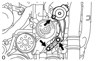
Install the bracket with the 3 bolts.
- Torque:
- 48.5 N*m (495 kgf*cm, 36 ft.*lbf)
2.INSTALL IDLER PULLEY BRACKET
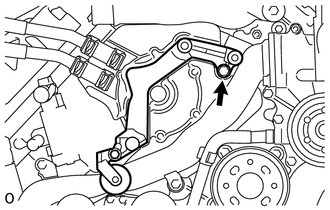
Install the bracket with the bolt.
- Torque:
- 48.5 N*m (495 kgf*cm, 36 ft.*lbf)
87120G
3.INSTALL VISCOUS WITH MAGNET CLUTCH HEATER ASSEMBLY
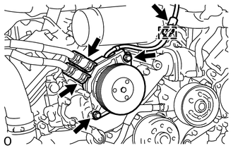
Install the heater assembly with the 2 bolts.
- Torque:
- 48.5 N*m (495 kgf*cm, 36 ft.*lbf)
Connect the 2 heater hoses.
Using pliers, grip the claws of the clips and slide the 2 clips.
Connect the connector and attach the clamp.
16630H
4.INSTALL IDLER PULLEY ASSEMBLY
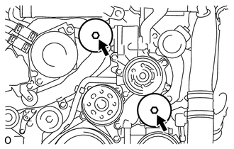
Install the 2 idler pulleys with the 2 bolts.
- Torque:
- 48.5 N*m (495 kgf*cm, 36 ft.*lbf)
16400
5.INSTALL RADIATOR ASSEMBLY
Install the radiator assembly (See page Engine / Hybrid System>1VD-FTV (COOLING)>RADIATOR>INSTALLATION).
16470
6.INSTALL RADIATOR RESERVE TANK ASSEMBLY
16711
7.INSTALL FAN SHROUD WITH FAN
15777
8.INSTALL OIL COOLER HOSE (w/ Air Cooled Transmission Oil Cooler)
16572D
9.INSTALL NO. 2 RADIATOR HOSE
16571C
10.INSTALL NO. 1 RADIATOR HOSE
44310
11.INSTALL VANE PUMP ASSEMBLY
44360
12.INSTALL VANE PUMP OIL RESERVOIR ASSEMBLY
87120H
13.INSTALL V-RIBBED BELT
17861
14.INSTALL INTAKE AIR CONNECTOR
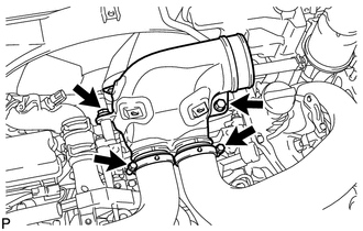
Connect the intake air connector to the No. 1 and No. 2 air cleaner pipes.
Install the connector with the 2 bolts.
- Torque:
- 21 N*m (214 kgf*cm, 15 ft.*lbf)
Tighten the 2 hose clamps.
- Torque:
- 6.3 N*m (64 kgf*cm, 56 in.*lbf)
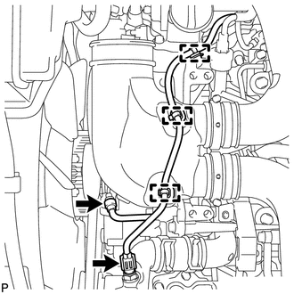
Attach the 3 wire harness clamps.
Connect the 2 connectors to the water temperature sensor and viscous heater.
17881
15. TEMPORARILY INSTALL NO. 1 AIR CLEANER HOSE
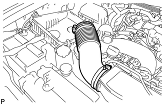
Temporarily install the air cleaner hose to the intake air connector.
17705
16.INSTALL AIR CLEANER CAP SUB-ASSEMBLY
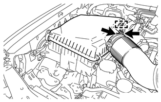
Connect the air cleaner cap to the air cleaner hose, and install the air cleaner cap with the 4 clamps.
Connect the connector and attach the wire harness clamp.
Align the protrusion of the air cleaner cap and concave portion of the air cleaner hose.
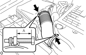
Tighten the 2 hose clamps as shown in the illustration.
| A | Below 15 mm (0.591 in.) |
12601E
17.INSTALL NO. 1 ENGINE COVER SUB-ASSEMBLY
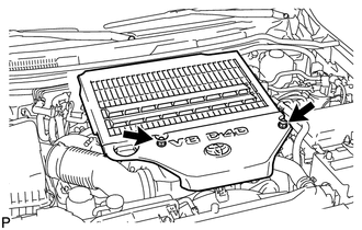
Install the engine cover with the 2 nuts.
- Torque:
- 8.0 N*m (82 kgf*cm, 71 in.*lbf)
82113
18.INSTALL NO. 3 ENGINE ROOM WIRE
53292A
19.INSTALL UPPER RADIATOR SUPPORT SEAL
20.ADD ENGINE COOLANT
51405A
21.INSTALL NO. 1 ENGINE UNDER COVER SUB-ASSEMBLY
53806
22.INSTALL FRONT FENDER SPLASH SHIELD SUB-ASSEMBLY LH
for Standard:
Install the front fender splash shield (See page Vehicle Exterior>EXTERIOR PANELS / TRIM>FRONT BUMPER(for Standard)>INSTALLATION).
w/ Winch:
Install the front fender splash shield (See page Vehicle Exterior>EXTERIOR PANELS / TRIM>FRONT BUMPER(w/ Winch)>INSTALLATION).
53805
23.INSTALL FRONT FENDER SPLASH SHIELD SUB-ASSEMBLY RH
for Standard:
Install the front fender splash shield (See page Vehicle Exterior>EXTERIOR PANELS / TRIM>FRONT BUMPER(for Standard)>INSTALLATION).
w/ Winch:
Install the front fender splash shield (See page Vehicle Exterior>EXTERIOR PANELS / TRIM>FRONT BUMPER(w/ Winch)>INSTALLATION).
24.CONNECT CABLE TO NEGATIVE BATTERY TERMINAL
- NOTICE:
-
When disconnecting the cable, some systems need to be initialized after the cable is reconnected (See page General>INTRODUCTION>REPAIR INSTRUCTION>INITIALIZATION).
25.CHECK FOR ENGINE COOLANT LEAKS