V35A-FTS ENGINE MECHANICAL CYLINDER HEAD GASKET REMOVAL
CAUTION / NOTICE / HINT
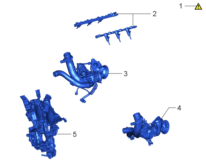
| Procedure | Part Name Code |

|

|

|
|
|---|---|---|---|---|---|
| 1 | INSTALL ENGINE STAND | - | ( ) |
- | - |
| 2 | DIRECT FUEL INJECTOR ASSEMBLY (for High Pressure) | 23250E | - | - | - |
| 3 | NO. 1 TURBOCHARGER SUB-ASSEMBLY | 17201A | - | - | - |
| 4 | NO. 2 TURBOCHARGER SUB-ASSEMBLY | 17208 | - | - | - |
| 5 | TIMING CHAIN COVER ASSEMBLY | 11310 | - | - | - |
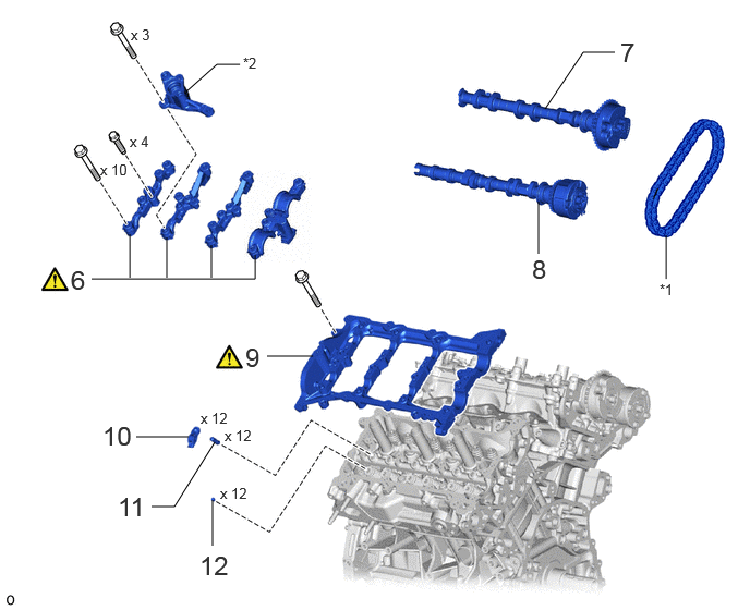
| Procedure | Part Name Code |
|
|
|
|
|---|---|---|---|---|---|
| 6 | CAMSHAFT BEARING CAP (for Bank 1) | - | () |
- | - |
| 7 | INTAKE CAMSHAFT SUB-ASSEMBLY RH | 13501B | - | - | - |
| 8 | EXHAUST CAMSHAFT SUB-ASSEMBLY RH | 13502C | - | - | - |
| 9 | CAMSHAFT HOUSING SUB-ASSEMBLY RH | 11103C | () |
- | - |
| 10 | VALVE ROCKER ARM SUB-ASSEMBLY RH | 13801L | - | - | - |
| 11 | VALVE LASH ADJUSTER ASSEMBLY (for Bank 1) | 13750 | - | - | - |
| 12 | VALVE STEM CAP (for Bank 1) | 13716 | - | - | - |
| *1 | NO. 2 CHAIN SUB-ASSEMBLY | *2 | FUEL PUMP LIFTER HOUSING RH |
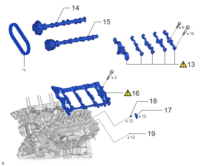
| Procedure | Part Name Code |
|
|
|
|
|---|---|---|---|---|---|
| 13 | CAMSHAFT BEARING CAP (for Bank 2) | - | () |
- | - |
| 14 | INTAKE CAMSHAFT SUB-ASSEMBLY LH | 13053B | - | - | - |
| 15 | EXHAUST CAMSHAFT SUB-ASSEMBLY LH | 13054A | - | - | - |
| 16 | CAMSHAFT HOUSING SUB-ASSEMBLY LH | 11104A | () |
- | - |
| 17 | VALVE ROCKER ARM SUB-ASSEMBLY LH | 13802B | - | - | - |
| 18 | VALVE LASH ADJUSTER ASSEMBLY (for Bank 2) | 13750 | - | - | - |
| 19 | VALVE STEM CAP (for Bank 2) | 13716 | - | - | - |
| *1 | NO. 2 CHAIN SUB-ASSEMBLY | - | - |
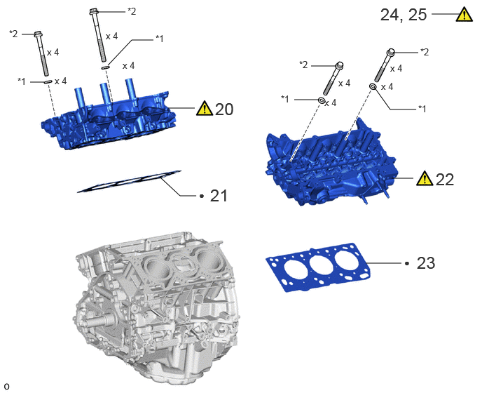
| Procedure | Part Name Code |
|
|
|
|
|---|---|---|---|---|---|
| 20 | CYLINDER HEAD SUB-ASSEMBLY RH | 1110A | () |
- | - |
| 21 | CYLINDER HEAD GASKET RH | 11115B | - | - | - |
| 22 | CYLINDER HEAD SUB-ASSEMBLY LH | 11102C | () |
- | - |
| 23 | CYLINDER HEAD GASKET LH | 11116H | - | - | - |
| 24 | INSPECT CYLINDER HEAD SET BOLT | 11101A | () |
- | - |
| 25 | INSPECT CYLINDER HEAD SUB-ASSEMBLY | - | () |
- | - |
| *1 | PLATE WASHER | *2 | CYLINDER HEAD SET BOLT |
| ● | Non-reusable part | - | - |
CAUTION / NOTICE / HINT
The necessary procedures (adjustment, calibration, initialization, or registration) that must be performed after parts are removed, installed, or replaced during the cylinder head gasket removal/installation are shown below.
| Replaced Part or Performed Procedure | Necessary Procedure | Effect/Inoperative Function when Necessary Procedure not Performed | Link |
|---|---|---|---|
| Battery terminal is disconnected/reconnected | Memorize steering angle neutral point | Parking assist monitor system | () |
| Multi-terrain monitor system | () |
||
| Panoramic view monitor system | () |
||
|
·
Cylinder head sub-assembly
·
Camshaft (for intake or exhaust camshaft)
·
Camshaft timing intake gear assembly
·
Camshaft timing exhaust gear assembly
·
Port fuel injector assembly
·
Direct fuel injector assembly
·
Air leaks from intake system
·
Gas leaks from exhaust system
·
Turbocharger sub-assembly |
Inspection after repairs |
·
Poor idle, etc.
·
Engine start function, etc. |
() |
| Engine assembly | Inspection after repair |
·
Poor idle, etc.
·
Engine start function, etc. |
() |
| Perform road test to allow TCM to learn |
·
Large shift shock
·
Engine overruns |
() |
|
| Automatic transmission assembly | ECU configuration | - | () |
| Update ECU security key | Vehicle control history (RoB) are stored | () |
|
| Automatic transmission fluid | ATF thermal degradation estimate reset | The value of the Data List item "ATF Thermal Degradation Estimate" is not estimated correctly. | () |
| Front bumper assembly (Including removal and installation) | Front television camera view adjustment | Panoramic view monitor system | () |
- HINT:
-
When the cable is disconnected/reconnected to the battery terminal, systems temporarily stop operating. However, each system has a function that completes learning the first time the system is used.
-
·
Learning completes when vehicle is driven
Effect/Inoperative Function When Necessary Procedures are not Performed Necessary Procedures Link Stop and start system Drive the vehicle until stop and start control is permitted (approximately 5 to 60 minutes). ( )Lighting system (EXT) Cornering lights Drive the vehicle straight ahead at 35 km/h (22 mph) or more for 5 seconds or more. ( )Pre-collision system Lane tracing assist system Lane departure alert system Adaptive high beam system
·Learning completes when vehicle is operated normally
Effect/Inoperative Function When Necessary Procedures are not Performed Necessary Procedures Link Power back door system Fully close the back door by hand.
- HINT:
-
Initialization is not necessary if the above procedures are performed while the back door is closed.
( )Air conditioning system After the ignition switch is turned to ON, the servo motor and expansion valve standard position is recognized. -
- NOTICE:
-
This procedure includes the removal of small-head bolts. Refer to Small-Head Bolts of Basic Repair Hint to identify the small-head bolts.
-
Click hereGeneral>INTRODUCTION>REPAIR INSTRUCTION>PRECAUTION
PROCEDURE

 1.INSTALL ENGINE STAND
23250E 2.REMOVE DIRECT FUEL INJECTOR ASSEMBLY (for High Pressure)
17201A 3.REMOVE NO. 1 TURBOCHARGER SUB-ASSEMBLY
17208 4.REMOVE NO. 2 TURBOCHARGER SUB-ASSEMBLY
11310 5.REMOVE TIMING CHAIN COVER ASSEMBLY
6.REMOVE CAMSHAFT BEARING CAP (for Bank 1)
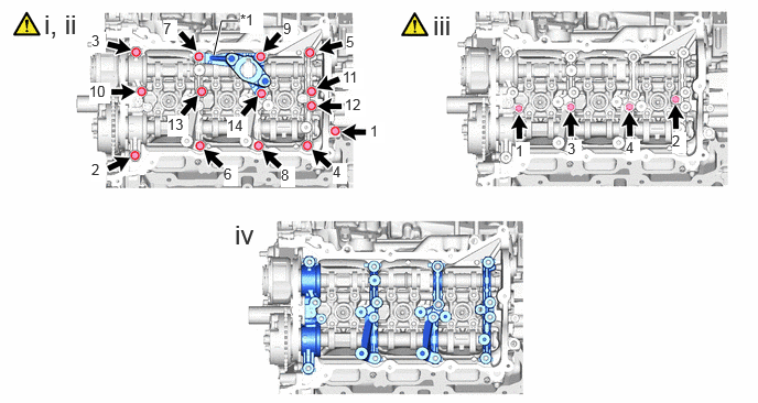
| *1 | Fuel Pump Lifter Housing RH | - | - |
Uniformly loosen and remove the 14 bearing cap bolts in several steps and in the sequence shown in the illustration.
Remove the fuel pump lifter housing RH.
Uniformly loosen and remove the 4 bearing cap bolts in several steps and in the sequence shown in the illustration.
- NOTICE:
-
Uniformly loosen the bolts while keeping the camshaft level.
Remove the camshaft bearing caps.
- HINT:
-
·
Remove the No. 1 camshaft bearing cap while holding down the chain plunger of the No. 2 chain tensioner assembly.
·Arrange the removed parts so that they can be reinstalled in their original locations.
13501B 7.REMOVE INTAKE CAMSHAFT SUB-ASSEMBLY RH

13502C 8.REMOVE EXHAUST CAMSHAFT SUB-ASSEMBLY RH

11103C 9.REMOVE CAMSHAFT HOUSING SUB-ASSEMBLY RH
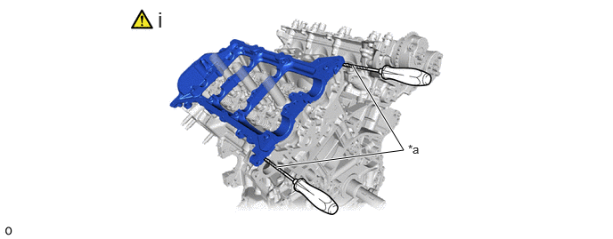
| *a | Protective Tape | - | - |
Remove the camshaft housing sub-assembly RH by prying between the cylinder head sub-assembly and camshaft housing sub-assembly RH with a screwdriver.
- NOTICE:
-
Be careful not to damage the contact surfaces of the cylinder head sub-assembly and camshaft housing sub-assembly RH.
- HINT:
-
Tape the screwdriver tip before use.
13801L 10.REMOVE VALVE ROCKER ARM SUB-ASSEMBLY RH

13750 11.REMOVE VALVE LASH ADJUSTER ASSEMBLY (for Bank 1)

13716 12.REMOVE VALVE STEM CAP (for Bank 1)

13.REMOVE CAMSHAFT BEARING CAP (for Bank 2)
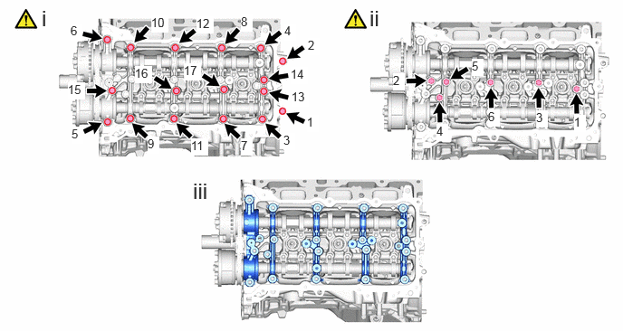
Uniformly loosen and remove the 17 bearing cap bolts in several steps and in the sequence shown in the illustration.
Uniformly loosen and remove the 6 bearing cap bolts in several steps and in the sequence shown in the illustration.
- NOTICE:
-
Uniformly loosen the bolts while keeping the camshaft level.
Remove the camshaft bearing caps.
- HINT:
-
·
Remove the No. 5 camshaft bearing cap while holding down the chain plunger of the No. 3 chain tensioner assembly.
·Arrange the removed parts so that they can be reinstalled in their original locations.
13053B 14.REMOVE INTAKE CAMSHAFT SUB-ASSEMBLY LH

13054A 15.REMOVE EXHAUST CAMSHAFT SUB-ASSEMBLY LH

11104A 16.REMOVE CAMSHAFT HOUSING SUB-ASSEMBLY LH
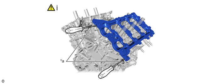
| *a | Protective Tape | - | - |
Remove the camshaft housing sub-assembly LH by prying between the cylinder head LH and camshaft housing sub-assembly LH with a screwdriver.
- NOTICE:
-
Be careful not to damage the contact surfaces of the cylinder head and camshaft housing sub-assembly LH.
- HINT:
-
Tape the screwdriver tip before use.
13802B 17.REMOVE VALVE ROCKER ARM SUB-ASSEMBLY LH

13750 18.REMOVE VALVE LASH ADJUSTER ASSEMBLY (for Bank 2)

13716 19.REMOVE VALVE STEM CAP (for Bank 2)

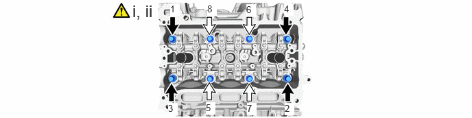
1110A 20.REMOVE CYLINDER HEAD SUB-ASSEMBLY RH

|
Bolt Length 140 mm (5.51 in.) |

|
Bolt Length 150 mm (5.90 in.) |
Using a 12 mm socket wrench, uniformly loosen the 8 bolts in the sequence shown in the illustration. Remove the 8 cylinder head set bolts and plate washers.
- NOTICE:
-
·
Be careful not to drop washers into the cylinder head sub-assembly RH.
·Cylinder head sub-assembly warpage or cracking could result from removing bolts in an incorrect order.
- HINT:
-
Be sure to keep separate the removed parts for each installation position.
Remove the cylinder head sub-assembly RH.
11115B 21.REMOVE CYLINDER HEAD GASKET RH

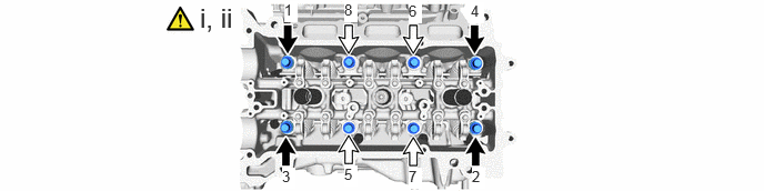
11102C 22.REMOVE CYLINDER HEAD SUB-ASSEMBLY LH
|
|
Bolt Length 140 mm (5.51 in.) |
|
Bolt Length 150 mm (5.90 in.) |
Using a 12 mm socket wrench, uniformly loosen the 8 bolts in the sequence shown in the illustration. Remove the 8 cylinder head set bolts and plate washers.
- NOTICE:
-
·
Be careful not to drop washers into the cylinder head sub-assembly LH.
·Cylinder head sub-assembly warpage or cracking could result from removing bolts in an incorrect order.
- HINT:
-
Be sure to keep separate the removed parts for each installation position.
Remove the cylinder head sub-assembly LH.
11116H 23.REMOVE CYLINDER HEAD GASKET LH

11101A 24.INSPECT CYLINDER HEAD SET BOLT
25.INSPECT CYLINDER HEAD SUB-ASSEMBLY