V35A-FTS LUBRICATION OIL PUMP INSTALLATION
CAUTION / NOTICE / HINT
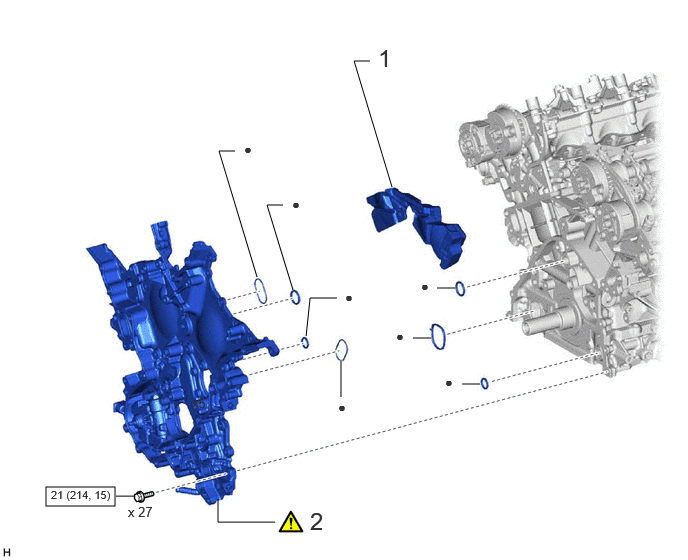
| Procedure | Part Name Code |

|

|

|
|
|---|---|---|---|---|---|
| 1 | NO. 6 ENGINE COVER | 12616 | - | - | - |
| 2 | TIMING CHAIN COVER ASSEMBLY | 11310 | ( ) |
- | - |

|
N*m (kgf*cm, ft.*lbf): Specified torque | ● | Non-reusable part |
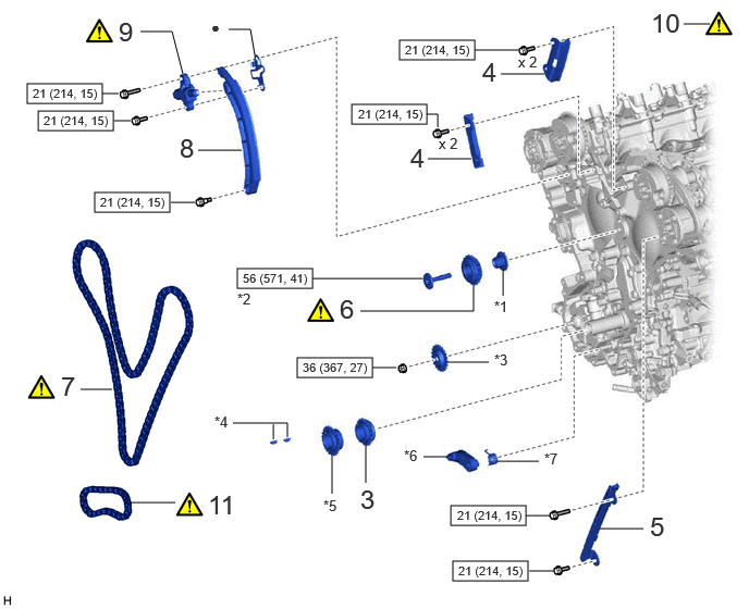
| Procedure | Part Name Code |
|
|
|
|
|---|---|---|---|---|---|
| 3 | CRANKSHAFT TIMING GEAR OR SPROCKET | 13521 | - | - | - |
| 4 | NO. 2 CHAIN VIBRATION DAMPER | 13562 | - | - | - |
| 5 | NO. 1 CHAIN VIBRATION DAMPER | 13561 | - | - | - |
| 6 | IDLE SPROCKET ASSEMBLY | 13530 | () |
- | - |
| 7 | NO. 1 CHAIN SUB-ASSEMBLY | 13506A | () |
- | - |
| 8 | CHAIN TENSIONER SLIPPER | 13559 | - | - | - |
| 9 | NO. 1 CHAIN TENSIONER ASSEMBLY | 13540 | () |
- | - |
| 10 | INSPECT VALVE TIMING | - | () |
- | - |
| 11 | OIL PUMP DRIVE CHAIN SUB-ASSEMBLY | 13507C | () |
- | - |
| *1 | NO. 1 IDLE GEAR SHAFT | *2 | NO. 2 IDLE GEAR SHAFT |
| *3 | OIL PUMP DRIVE SHAFT SPROCKET | *4 | CRANKSHAFT TIMING GEAR KEY |
| *5 | OIL PUMP DRIVE SPROCKET | *6 | CHAIN TENSIONER PLATE |
| *7 | CHAIN DAMPER SPRING | - | - |
|
|
N*m (kgf*cm, ft.*lbf): Specified torque | ● | Non-reusable part |
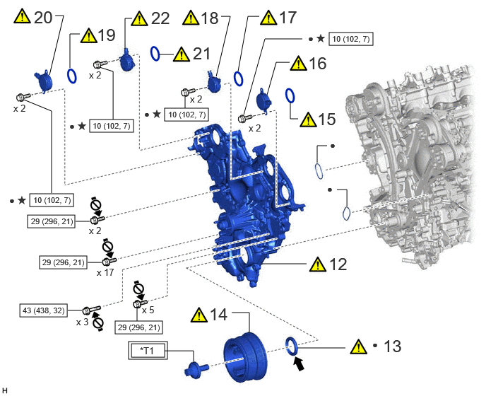
| Procedure | Part Name Code |
|
|
|
|
|---|---|---|---|---|---|
| 12 | TIMING CHAIN OR BELT COVER SUB-ASSEMBLY | 11302 | () |
- | - |
| 13 | TIMING CHAIN CASE OIL SEAL | 11301C | () |
- | - |
| 14 | CRANKSHAFT PULLEY | 13471 | () |
- | - |
| 15 | CAM TIMING OIL CONTROL SOLENOID LH O-RING (for Exhaust Side of Bank 2) | 15370E | () |
- | - |
| 16 | CAM TIMING OIL CONTROL SOLENOID ASSEMBLY LH (for Exhaust Side of Bank 2) | 15370C | () |
- | - |
| 17 | CAM TIMING OIL CONTROL SOLENOID LH O-RING (for Intake Side of Bank 2) | 15370E | () |
- | - |
| 18 | CAM TIMING OIL CONTROL SOLENOID ASSEMBLY LH (for Intake Side of Bank 2) | 15370C | () |
- | - |
| 19 | CAM TIMING OIL CONTROL SOLENOID RH O-RING (for Exhaust Side of Bank 1) | 15370D | () |
- | - |
| 20 | CAM TIMING OIL CONTROL SOLENOID ASSEMBLY RH (for Exhaust Side of Bank 1) | 15370B | () |
- | - |
| 21 | CAM TIMING OIL CONTROL SOLENOID RH O-RING (for Intake Side of Bank 1) | 15370D | () |
- | - |
| 22 | CAM TIMING OIL CONTROL SOLENOID ASSEMBLY RH (for Intake Side of Bank 1) | 15370B | () |
- | - |

|
Tightening torque for "Major areas involving basic vehicle performance such as moving/turning/stopping": N*m (kgf*cm, ft.*lbf) |
|
N*m (kgf*cm, ft.*lbf): Specified torque |
| ● | Non-reusable part |

|
MP grease |
| ★ | Precoated part |

|
Do not apply lubricants to the threads |
| *T1 | 1st: 120 (1224, 89) 2nd: 365 (3722, 269) |
- | - |
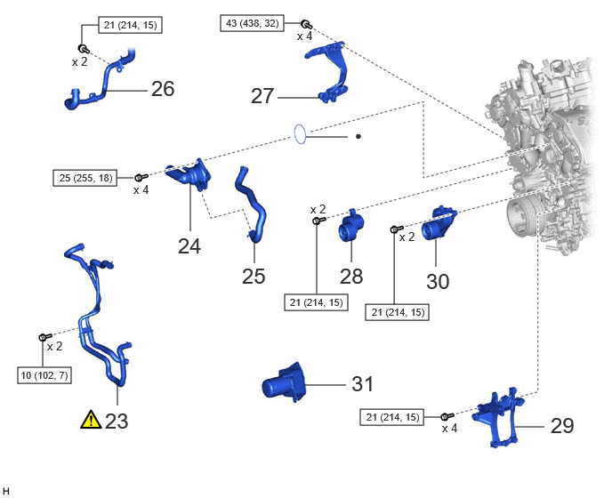
| Procedure | Part Name Code |
|
|
|
|
|---|---|---|---|---|---|
| 23 | WATER BY-PASS HOSE ASSEMBLY | 16260 | () |
- | - |
| 24 | WATER INLET SUB-ASSEMBLY WITH THERMOSTAT | 16031 | - | - | - |
| 25 | NO. 14 WATER BY-PASS HOSE | 1629A | - | - | - |
| 26 | WATER BY-PASS PIPE | - | - | - | - |
| 27 | GENERATOR BRACKET SUB-ASSEMBLY | 12501 | - | - | - |
| 28 | V-RIBBED BELT TENSIONER SUB-ASSEMBLY | 16601 | - | - | - |
| 29 | CHAIN COVER AND COMPRESSOR BRACKET SUB-ASSEMBLY | 12502 | - | - | - |
| 30 | V-RIBBED BELT TENSIONER ASSEMBLY | 16620D | - | - | - |
| 31 | OIL COOLER ASSEMBLY WITH OIL FILTER SUB-ASSEMBLY | - | - | - | - |
|
|
N*m (kgf*cm, ft.*lbf): Specified torque | ● | Non-reusable part |
| Procedure | Part Name Code |
|
|
|
|
|---|---|---|---|---|---|
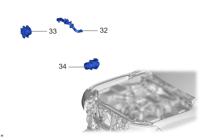
| 32 | WATER OUTLET PIPE WITH WATER BY-PASS JOINT | - | - | - | - |
| 33 | GENERATOR ASSEMBLY | 27060 | - | - | - |
| 34 | COMPRESSOR WITH MAGNET CLUTCH | - | - | - | - |
CAUTION / NOTICE / HINT
- NOTICE:
-
This procedure includes the installation of small-head bolts. Refer to Small-Head Bolts of Basic Repair Hint to identify the small-head bolts.
-
Click hereGeneral>INTRODUCTION>REPAIR INSTRUCTION>PRECAUTION
PROCEDURE

 12616 1.INSTALL NO. 6 ENGINE COVER
11310 2.INSTALL TIMING CHAIN COVER ASSEMBLY
|
|
Click here() |
13521 3.INSTALL CRANKSHAFT TIMING GEAR OR SPROCKET
13562 4.INSTALL NO. 2 CHAIN VIBRATION DAMPER
13561 5.INSTALL NO. 1 CHAIN VIBRATION DAMPER
13530 6.INSTALL IDLE SPROCKET ASSEMBLY
|
|
Click here() |
13506A 7.INSTALL NO. 1 CHAIN SUB-ASSEMBLY
|
|
Click here() |
13559 8.INSTALL CHAIN TENSIONER SLIPPER
13540 9.INSTALL NO. 1 CHAIN TENSIONER ASSEMBLY
|
|
Click here() |
10.INSPECT VALVE TIMING
|
|
Click here() |
13507C 11.INSTALL OIL PUMP DRIVE CHAIN SUB-ASSEMBLY
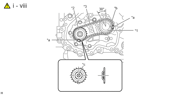
| *1 | Oil Pump Drive Sprocket | *2 | Oil Pump Drive Shaft Sprocket |
| *3 | Oil Pump Drive Chain Sub-assembly | - | - |
| *a | Mark Plate | *b | Timing Mark |
| *c | D Cut Plane | - | - |
Rotate the crankshaft timing gear key position 30° counterclockwise as shown in the illustration.
Set the D cut plane of the oil pump shaft at the position shown in the illustration.
Align the mark plates (yellow) on the oil pump drive sprocket, oil pump drive shaft sprocket and oil pump drive chain sub-assembly with the timing marks.
Install them to the oil pump shaft and crankshaft.
Temporarily install the oil pump drive shaft gear nut.
While pushing the chain damper spring, install the chain tensioner plate and chain damper spring.
Using the hexagonal portion of the camshaft, secure the camshaft.
Tighten the oil pump drive shaft gear nut.
- Torque:
- 36 N*m (367 kgf*cm, 27 ft.*lbf)
11302 12.INSTALL TIMING CHAIN OR BELT COVER SUB-ASSEMBLY
Temporarily install the timing chain or belt cover sub-assembly with the 27 bolts.
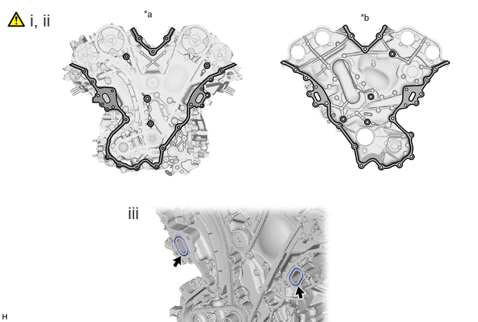
| *a | Timing Chain Cover Assembly Side | *b | Timing Chain or Belt Cover Sub-assembly Side |

|
Clean and Degrease | - | - |
Remove any old packing remaining on the sealing surfaces before applying seal packing.
Clean the contact surfaces of the timing chain cover assembly, timing chain or belt cover sub-assembly and confirm that there is no oil, moisture or other foreign matter on the surfaces.
- NOTICE:
-
·
Be sure to clean and degrease the contact surfaces, especially the surfaces indicated in the illustration.
·Check the bolts and bolt holes, and clean and degrease them.
Install 2 new water pump gaskets to the timing chain cover assembly.
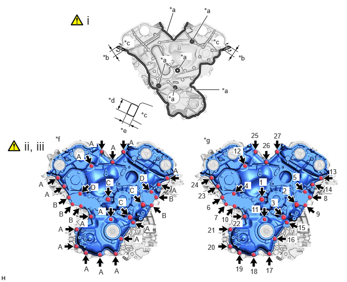
| *a | Standard Seal Packing Diameter 3.0 to 4.0 mm (0.118 to 0.157 in.) |
*b | Seal Packing Width 35 mm (1.38 in.) |
| *c | Thick Coating Cross-section | *d | Wide Seal Packing Diameter 4.0 to 8.0 mm (0.157 to 0.314 in.) |
| *e | Wide Seal Packing Diameter 3.0 to 5.0 mm (0.118 to 0.197 in.) |
*f | Type of Bolt |
| *g | Tightening Order | - | - |

|
Seal Packing | - | - |
Apply seal packing in a continuous line to the timing chain or belt cover sub-assembly as shown in the illustration.
- NOTICE:
-
·
Using non-residue solvent, clean and remove any oil from the installation surface.
·Check the bolts and bolt holes, and clean and degrease them.
·Install the timing chain or belt cover sub-assembly within 3 minutes and tighten the bolts within 15 minutes of applying seal packing.
·Do not add engine oil for at least 2 hours after installing the timing chain cover assembly.
·Do not start the engine for at least 2 hours after installing the timing chain cover assembly.
Temporarily install the timing chain or belt cover sub-assembly with the 27 bolts.
- Bolt Length:
-
Item Length A 35 mm (1.38 in.) B 80 mm (3.15 in.) C 90 mm (3.54 in.) D 55 mm (2.17 in.)
- NOTICE:
-
Make sure that there is no oil on the bolt threads.
Tighten the 27 bolts in several steps, in the sequence shown in the illustration.
- Torque:
- Bolts A, B and D : 29 N*m (296 kgf*cm, 21 ft.*lbf)
- Bolt C : 43 N*m (438 kgf*cm, 32 ft.*lbf)
11301C 13.INSTALL TIMING CHAIN CASE OIL SEAL
|
|
Click here() |
13471 14.INSTALL CRANKSHAFT PULLEY
|
|
Click here() |
15370E 15.INSTALL CAM TIMING OIL CONTROL SOLENOID LH O-RING (for Exhaust Side of Bank 2)
|
|
Click here() |
15370C 16.INSTALL CAM TIMING OIL CONTROL SOLENOID ASSEMBLY LH (for Exhaust Side of Bank 2)
|
|
Click here() |
15370E 17.INSTALL CAM TIMING OIL CONTROL SOLENOID LH O-RING (for Intake Side of Bank 2)
|
|
Click here() |
15370C 18.INSTALL CAM TIMING OIL CONTROL SOLENOID ASSEMBLY LH (for Intake Side of Bank 2)
|
|
Click here() |
15370D 19.INSTALL CAM TIMING OIL CONTROL SOLENOID RH O-RING (for Exhaust Side of Bank 1)
|
|
Click here() |
15370B 20.INSTALL CAM TIMING OIL CONTROL SOLENOID ASSEMBLY RH (for Exhaust Side of Bank 1)
|
|
Click here() |
15370D 21.INSTALL CAM TIMING OIL CONTROL SOLENOID RH O-RING (for Intake Side of Bank 1)
|
|
Click here() |
15370B 22.INSTALL CAM TIMING OIL CONTROL SOLENOID ASSEMBLY RH (for Intake Side of Bank 1)
|
|
Click here() |
16260 23.INSTALL WATER BY-PASS HOSE ASSEMBLY
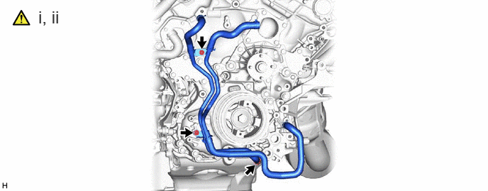
Using an 8 mm socket wrench, install the water by-pass hose assembly with the 2 bolts.
- Torque:
- 10 N*m (102 kgf*cm, 7 ft.*lbf)
Connect the water by-pass hose assembly to the timing chain cover assembly, and slide the clip to secure the hose.
16031 24.INSTALL WATER INLET SUB-ASSEMBLY WITH THERMOSTAT
- Torque:
- 25 N*m (255 kgf*cm, 18 ft.*lbf)
1629A 25.INSTALL NO. 14 WATER BY-PASS HOSE
26.CONNECT WATER BY-PASS PIPE
- Torque:
- 21 N*m (214 kgf*cm, 15 ft.*lbf)
12501 27.INSTALL GENERATOR BRACKET SUB-ASSEMBLY
- Torque:
- 43 N*m (438 kgf*cm, 32 ft.*lbf)
16601 28.INSTALL V-RIBBED BELT TENSIONER SUB-ASSEMBLY
- Torque:
- 21 N*m (214 kgf*cm, 15 ft.*lbf)
12502 29.INSTALL CHAIN COVER AND COMPRESSOR BRACKET SUB-ASSEMBLY
- Torque:
- 21 N*m (214 kgf*cm, 15 ft.*lbf)
16620D 30.INSTALL V-RIBBED BELT TENSIONER ASSEMBLY
- Torque:
- 21 N*m (214 kgf*cm, 15 ft.*lbf)
31.INSTALL OIL COOLER ASSEMBLY WITH OIL FILTER SUB-ASSEMBLY
32.INSTALL WATER OUTLET PIPE WITH WATER BY-PASS JOINT
27060 33.INSTALL GENERATOR ASSEMBLY
for DENSO Made:
Click herePower Source / Network>V35A-FTS (BATTERY / CHARGING)>GENERATOR (for DENSO Made)>INSTALLATION
for VALEO Made:
Click herePower Source / Network>V35A-FTS (BATTERY / CHARGING)>GENERATOR (for VALEO Made)>INSTALLATION
34.INSTALL COMPRESSOR WITH MAGNET CLUTCH