V35A-FTS ENGINE MECHANICAL CAMSHAFT INSTALLATION
CAUTION / NOTICE / HINT
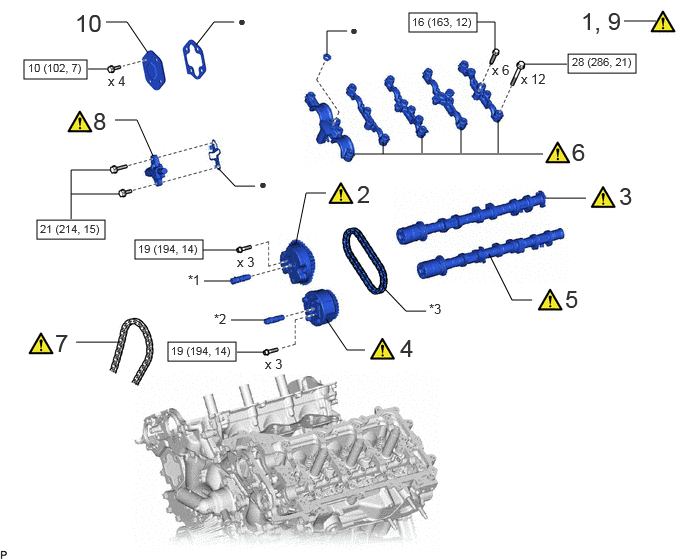
| Procedure | Part Name Code |

|

|

|
|
|---|---|---|---|---|---|
| 1 | SET NO. 1 CYLINDER TO TDC/COMPRESSION (for Bank 2) | - | ( ) |
- | - |
| 2 | CAMSHAFT TIMING INTAKE GEAR ASSEMBLY LH (for Intake Side of Bank 2) | 13060B | () |
- | - |
| 3 | INTAKE CAMSHAFT SUB-ASSEMBLY LH | 13053B | () |
- | - |
| 4 | CAMSHAFT TIMING EXHAUST GEAR ASSEMBLY LH (for Exhaust Side of Bank 2) | 13080 | () |
- | - |
| 5 | EXHAUST CAMSHAFT SUB-ASSEMBLY LH | 13054A | () |
- | - |
| 6 | CAMSHAFT BEARING CAP (for Bank 2) | - | () |
- | - |
| 7 | NO. 1 CHAIN SUB-ASSEMBLY (for Bank 2) | 13506A | () |
- | - |
| 8 | NO. 1 CHAIN TENSIONER ASSEMBLY (for Bank 2) | 13540 | () |
- | - |
| 9 | INSPECT VALVE TIMING | - | () |
- | - |
| 10 | TIMING CHAIN COVER PLATE | 11324 | - | - | - |
| *1 | CAMSHAFT TIMING OIL CONTROL VALVE ASSEMBLY (INTAKE CAMSHAFT TIMING GEAR BOLT ASSEMBLY) | *2 | CAMSHAFT TIMING OIL CONTROL VALVE ASSEMBLY (EXHAUST CAMSHAFT TIMING GEAR BOLT ASSEMBLY) |
| *3 | NO. 2 CHAIN SUB-ASSEMBLY | - | - |

|
N*m (kgf*cm, ft.*lbf): Specified torque | ● | Non-reusable part |
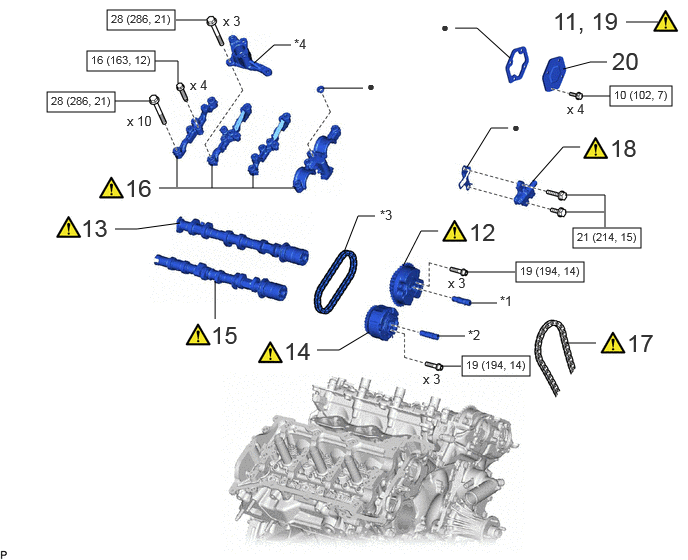
| Procedure | Part Name Code |
|
|
|
|
|---|---|---|---|---|---|
| 11 | SET NO. 1 CYLINDER TO TDC/COMPRESSION (for Bank 1) | - | () |
- | - |
| 12 | CAMSHAFT TIMING INTAKE GEAR ASSEMBLY RH (for Intake Side of Bank 1) | 13050B | () |
- | - |
| 13 | INTAKE CAMSHAFT SUB-ASSEMBLY RH | 13501B | () |
- | - |
| 14 | CAMSHAFT TIMING EXHAUST GEAR ASSEMBLY RH (for Exhaust Side of Bank 1) | 13070 | () |
- | - |
| 15 | EXHAUST CAMSHAFT SUB-ASSEMBLY RH | 13502C | () |
- | - |
| 16 | CAMSHAFT BEARING CAP (for Bank 1) | - | () |
- | - |
| 17 | NO. 1 CHAIN SUB-ASSEMBLY (for Bank 1) | 13506A | () |
- | - |
| 18 | NO. 1 CHAIN TENSIONER ASSEMBLY (for Bank 1) | 13540 | () |
- | - |
| 19 | INSPECT VALVE TIMING | - | () |
- | - |
| 20 | TIMING CHAIN COVER PLATE | 11324 | - | - | - |
| *1 | CAMSHAFT TIMING OIL CONTROL VALVE ASSEMBLY (INTAKE CAMSHAFT TIMING GEAR BOLT ASSEMBLY) | *2 | CAMSHAFT TIMING OIL CONTROL VALVE ASSEMBLY (EXHAUST CAMSHAFT TIMING GEAR BOLT ASSEMBLY) |
| *3 | NO. 2 CHAIN SUB-ASSEMBLY | *4 | FUEL PUMP LIFTER HOUSING RH |
|
|
N*m (kgf*cm, ft.*lbf): Specified torque | ● | Non-reusable part |
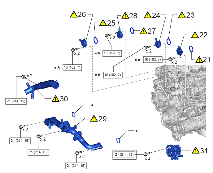
| Procedure | Part Name Code |
|
|
|
|
|---|---|---|---|---|---|
| 21 | CAM TIMING OIL CONTROL SOLENOID LH O-RING (for Exhaust Side of Bank 2) | 15370E | () |
- | - |
| 22 | CAM TIMING OIL CONTROL SOLENOID ASSEMBLY LH (for Exhaust Side of Bank 2) | 15370C | () |
- | - |
| 23 | CAM TIMING OIL CONTROL SOLENOID LH O-RING (for Intake Side of Bank 2) | 15370E | () |
- | - |
| 24 | CAM TIMING OIL CONTROL SOLENOID ASSEMBLY LH (for Intake Side of Bank 2) | 15370C | () |
- | - |
| 25 | CAM TIMING OIL CONTROL SOLENOID RH O-RING (for Exhaust Side of Bank 1) | 15370D | () |
- | - |
| 26 | CAM TIMING OIL CONTROL SOLENOID ASSEMBLY RH (for Exhaust Side of Bank 1) | 15370B | () |
- | - |
| 27 | CAM TIMING OIL CONTROL SOLENOID RH O-RING (for Intake Side of Bank 1) | 15370D | () |
- | - |
| 28 | CAM TIMING OIL CONTROL SOLENOID ASSEMBLY RH (for Intake Side of Bank 1) | 15370B | () |
- | - |
| 29 | WATER OUTLET PIPE WITH WATER BY-PASS JOINT | - | () |
- | - |
| 30 | WATER INLET PIPE WITH WATER INLET HOSE | - | () |
- | - |
| 31 | VANE PUMP ASSEMBLY | 44310 | () |
- | - |

|
Tightening torque for "Major areas involving basic vehicle performance such as moving/turning/stopping": N*m (kgf*cm, ft.*lbf) |
|
N*m (kgf*cm, ft.*lbf): Specified torque |
| ● | Non-reusable part | ★ | Precoated part |
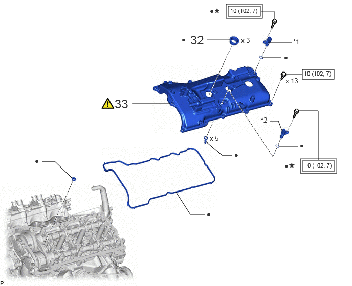
| Procedure | Part Name Code |
|
|
|
|
|---|---|---|---|---|---|
| 32 | SPARK PLUG TUBE GASKET LH | 11193A | - | - | - |
| 33 | CYLINDER HEAD COVER SUB-ASSEMBLY LH | 11202 | () |
- | - |
| *1 | CAMSHAFT POSITION SENSOR (for Intake Side of Bank 2) | *2 | CAMSHAFT POSITION SENSOR (for Exhaust Side of Bank 2) |
|
|
Tightening torque for "Major areas involving basic vehicle performance such as moving/turning/stopping": N*m (kgf*cm, ft.*lbf) |
|
N*m (kgf*cm, ft.*lbf): Specified torque |
| ● | Non-reusable part | ★ | Precoated part |
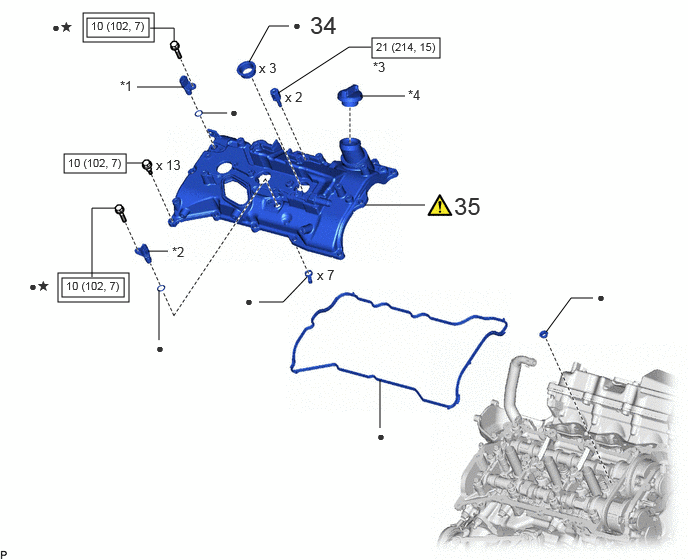
| Procedure | Part Name Code |
|
|
|
|
|---|---|---|---|---|---|
| 34 | SPARK PLUG TUBE GASKET RH | 11193B | - | - | - |
| 35 | CYLINDER HEAD COVER SUB-ASSEMBLY RH | 11201M | () |
- | - |
| *1 | CAMSHAFT POSITION SENSOR (for Intake Side of Bank 1) | *2 | CAMSHAFT POSITION SENSOR (for Exhaust Side of Bank 1) |
| *3 | NO. 1 INTERCOOLER AIR GUIDE | *4 | OIL FILLER CAP ASSEMBLY |
|
|
Tightening torque for "Major areas involving basic vehicle performance such as moving/turning/stopping": N*m (kgf*cm, ft.*lbf) |
|
N*m (kgf*cm, ft.*lbf): Specified torque |
| ● | Non-reusable part | ★ | Precoated part |
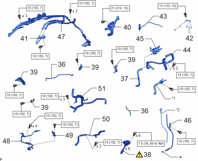
| Procedure | Part Name Code |
|
|
|
|
|---|---|---|---|---|---|
| 36 | VACUUM HOSE | - | - | - | - |
| 37 | NO. 4 FUEL VAPOR FEED HOSE | 2382A | - | - | - |
| 38 | IGNITION COIL ASSEMBLY | 19500 | () |
- | - |
| 39 | WIRE HARNESS CLAMP BRACKET | - | - | - | - |
| 40 | NO. 3 WATER BY-PASS PIPE | 16279 | - | - | - |
| 41 | NO. 1 TURBO WATER PIPE SUB-ASSEMBLY | 16027 | - | - | - |
| 42 | NO. 2 WIRING HARNESS CLAMP BRACKET | 82715X | - | - | - |
| 43 | AIR FUEL RATIO SENSOR | - | - | - | - |
| 44 | FUEL VAPOR FEED PIPE | 23818 | - | - | - |
| 45 | PURGE VSV | 17650G | - | - | - |
| 46 | ENGINE OIL LEVEL DIPSTICK GUIDE | 11452 | - | - | - |
| 47 | INTERCOOLER COOLING WATER PIPE ASSEMBLY AND TURBO WATER HOSE | - | - | - | - |
| 48 | FUEL INLET PIPE SUB-ASSEMBLY | 23804J | - | - | - |
| 49 | NO. 2 V-BANK COVER BRACKET | 11256 | - | - | - |
| 50 | NO. 6 WATER BY-PASS PIPE | 1628A | - | - | - |
| 51 | NO. 5 WATER BY-PASS PIPE | 16289 | - | - | - |
| *1 | NO. 2 TURBO WATER PIPE SUB-ASSEMBLY | *2 | ENGINE OIL LEVEL DIPSTICK |
|
|
N*m (kgf*cm, ft.*lbf): Specified torque | ● | Non-reusable part |
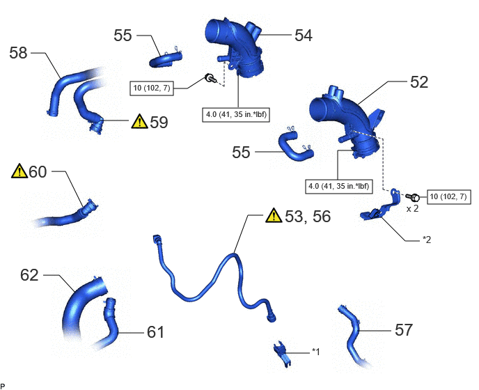
| Procedure | Part Name Code |
|
|
|
|
|---|---|---|---|---|---|
| 52 | NO. 2 AIR INLET DUCT | 17312D | - | - | - |
| 53 | INSTALL FUEL TUBE SUB-ASSEMBLY | 23901 | () |
- | - |
| 54 | NO. 1 AIR INLET DUCT | 17311 | - | - | - |
| 55 | NO. 2 PCV HOSE | 12262 | - | - | - |
| 56 | CONNECT FUEL TUBE SUB-ASSEMBLY | 23901 | () |
- | - |
| 57 | NO. 1 FUEL VAPOR FEED HOSE | 23826 | - | - | - |
| 58 | HEATER WATER HOSE OUTLET A | - | - | - | - |
| 59 | WATER HOSE SUB-ASSEMBLY | 87209 | () |
- | - |
| 60 | NO. 4 WATER BY-PASS HOSE ASSEMBLY | 162A0 | () |
- | - |
| 61 | NO. 4 WATER BY-PASS HOSE | 16267C | - | - | - |
| 62 | NO. 2 RADIATOR HOSE | 16572D | - | - | - |
| *1 | COOL AIR INLET BRACKET | *2 | FUEL PIPE CLAMP |
|
|
N*m (kgf*cm, ft.*lbf): Specified torque | - | - |
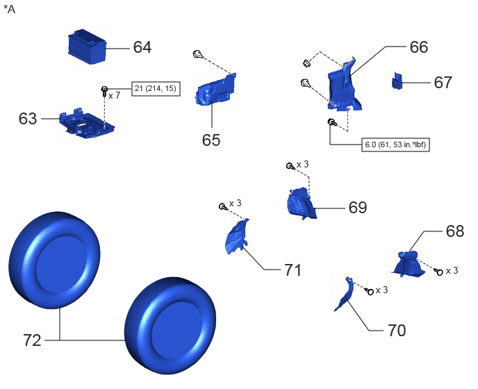
| Procedure | Part Name Code |
|
|
|
|
|---|---|---|---|---|---|
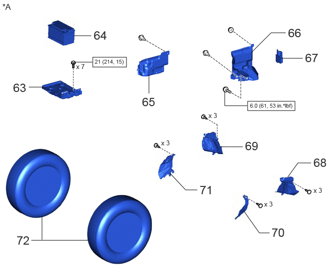
| 63 | BATTERY CARRIER ASSEMBLY | 74410 | - | - | - |
| 64 | BATTERY | 28800 | - | - | - |
| 65 | ENGINE SIDE UNDER COVER RH | 51448M | - | - | - |
| 66 | UPPER ENGINE SIDE UNDER COVER PLATE LH | 51478C | - | - | - |
| 67 | REAR ENGINE SIDE UNDER COVER ASSEMBLY LH | 51470C | - | - | - |
| 68 | FRONT FENDER APRON TRIM PACKING D | 53785B | - | - | - |
| 69 | FRONT FENDER APRON TRIM PACKING C | 53784 | - | - | - |
| 70 | FRONT FENDER APRON TRIM PACKING B | 53783 | - | - | - |
| 71 | FRONT FENDER APRON TRIM PACKING A | 53782 | - | - | - |
| 72 | FRONT WHEEL | - | - | - | - |
| *A | for LHD | - | - |
|
|
N*m (kgf*cm, ft.*lbf): Specified torque | - | - |
| Procedure | Part Name Code |
|
|
|
|
|---|---|---|---|---|---|
| 63 | BATTERY CARRIER ASSEMBLY | 74410 | - | - | - |
| 64 | BATTERY | 28800 | - | - | - |
| 65 | ENGINE SIDE UNDER COVER RH | 51448M | - | - | - |
| 66 | UPPER ENGINE SIDE UNDER COVER PLATE LH | 51478C | - | - | - |
| 67 | REAR ENGINE SIDE UNDER COVER ASSEMBLY LH | 51470C | - | - | - |
| 68 | FRONT FENDER APRON TRIM PACKING D | 53785B | - | - | - |
| 69 | FRONT FENDER APRON TRIM PACKING C | 53784 | - | - | - |
| 70 | FRONT FENDER APRON TRIM PACKING B | 53783 | - | - | - |
| 71 | FRONT FENDER APRON TRIM PACKING A | 53782 | - | - | - |
| 72 | FRONT WHEEL | - | - | - | - |
| *A | for RHD | - | - |
|
|
N*m (kgf*cm, ft.*lbf): Specified torque | - | - |
| Procedure | Part Name Code |
|
|
|
|
|---|---|---|---|---|---|
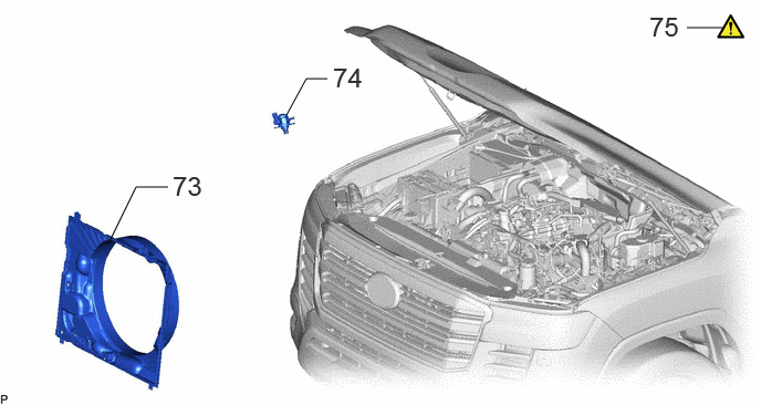
| 73 | FAN SHROUD | 16711 | - | - | - |
| 74 | FUEL (ENGINE ROOM SIDE) PUMP ASSEMBLY | 23100X | - | - | - |
| 75 | INSPECT IGNITION TIMING | - | () |
- | - |
CAUTION / NOTICE / HINT
- NOTICE:
-
This procedure includes the installation of small-head bolts. Refer to Small-Head Bolts of Basic Repair Hint to identify the small-head bolts.
-
Click hereGeneral>INTRODUCTION>REPAIR INSTRUCTION>PRECAUTION
- HINT:
-
Perform "Inspection After Repairs" after replacing the intake camshaft sub-assembly RH, exhaust camshaft sub-assembly RH, intake camshaft sub-assembly LH, exhaust camshaft sub-assembly LH, camshaft timing gear assembly or camshaft timing exhaust gear assembly.
-
Click hereEngine / Hybrid System>V35A-FTS (ENGINE CONTROL)>SFI SYSTEM>INITIALIZATION
PROCEDURE

 1.SET NO. 1 CYLINDER TO TDC/COMPRESSION (for Bank 2)
|
|
Click here() |
13060B 2.INSTALL CAMSHAFT TIMING INTAKE GEAR ASSEMBLY LH (for Intake Side of Bank 2)
|
|
|
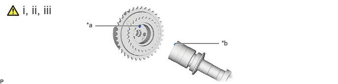
| *a | Pin Hole | *b | Straight Pin |
Put the camshaft timing intake gear assembly LH and intake camshaft sub-assembly LH together by aligning the pin hole and straight pin.
Temporarily install the camshaft timing oil control valve assembly (intake camshaft timing gear bolt assembly) to the camshaft timing exhaust gear assembly LH.
- NOTICE:
-
If the camshaft timing oil control valve assembly (intake camshaft timing gear bolt assembly) has been struck or dropped, replace it.
Temporarily install the 3 bolts.
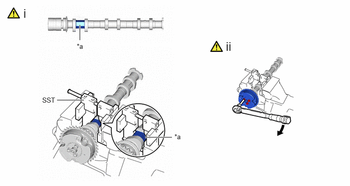
| *a | Hexagonal Portion | - | - |
Using SST, grip the hexagonal portion, and then secure SST and intake camshaft sub-assembly LH in a vise as shown in the illustration.
- SST
-
09212-31010
- NOTICE:
-
·
Do not damage the intake camshaft sub-assembly LH.
·Never grip areas other than the hexagonal portion, as this may cause damage.
Using a 5 mm hexagon socket wrench, install the camshaft timing intake gear assembly LH with the 3 bolts and install the camshaft timing oil control valve assembly (intake camshaft timing gear bolt assembly).
- Torque:
- 19 N*m (194 kgf*cm, 14 ft.*lbf)
13053B 3.INSTALL INTAKE CAMSHAFT SUB-ASSEMBLY LH
|
|
|
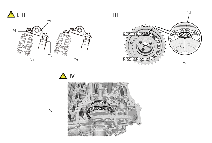
| *1 | Valve Stem Cap | *2 | No. 1 Valve Rocker Arm Sub-assembly |
| *3 | Valve Lash Adjuster Assembly | - | - |
| *a | CORRECT | *b | INCORRECT |
| *c | Timing Mark | *d | Mark Plate (Pink) |
| *e | Place on camshaft timing gear assembly | - | - |
Clean the camshaft housing LH and camshaft journals and apply engine oil to them.
Make sure that the No. 1 valve rocker arm sub-assembly is installed as shown in the illustration.
Align the mark plate (pink) with the timing mark of the camshaft timing gear assembly as shown in the illustration and install the No. 2 chain sub-assembly to the camshaft timing gear assembly.
Install the No. 1 chain sub-assembly to the camshaft timing gear assembly, and then set the camshaft timing gear assembly to the camshaft housing LH.
- HINT:
-
·
Place the No. 1 chain sub-assembly on the camshaft timing gear but do not engage the teeth of the sprocket and the No. 1 chain sub-assembly.
·Install the camshaft timing gear so that the timing mark is facing upward.
13080 4.INSTALL CAMSHAFT TIMING EXHAUST GEAR ASSEMBLY LH (for Exhaust Side of Bank 2)
|
|
|
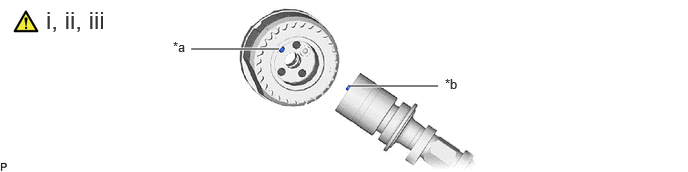
| *a | Pin Hole | *b | Straight Pin |
Put the camshaft timing exhaust gear assembly LH and exhaust camshaft sub-assembly LH together by aligning the pin hole and straight pin.
Temporarily install the camshaft timing oil control valve assembly (exhaust camshaft timing gear bolt assembly) to the camshaft timing exhaust gear assembly LH.
- NOTICE:
-
If the camshaft timing oil control valve assembly (exhaust camshaft timing gear bolt assembly) has been struck or dropped, replace it.
Temporarily install the 3 bolts.
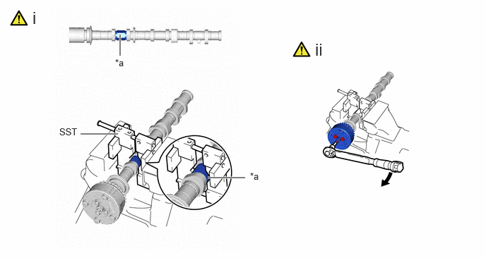
| *a | Hexagonal Portion | - | - |
Using SST, grip the hexagonal portion, and then secure SST and exhaust camshaft sub-assembly LH in a vise as shown in the illustration.
- SST
-
09212-31010
- NOTICE:
-
·
Do not damage the exhaust camshaft sub-assembly LH.
·Never grip areas other than the hexagonal portion, as this may cause damage.
Using a 5 mm hexagon socket wrench, install the camshaft timing exhaust gear assembly LH with the 3 bolts and install the camshaft timing oil control valve assembly (exhaust camshaft timing gear bolt assembly).
- Torque:
- 19 N*m (194 kgf*cm, 14 ft.*lbf)
13054A 5.INSTALL EXHAUST CAMSHAFT SUB-ASSEMBLY LH
|
|
|
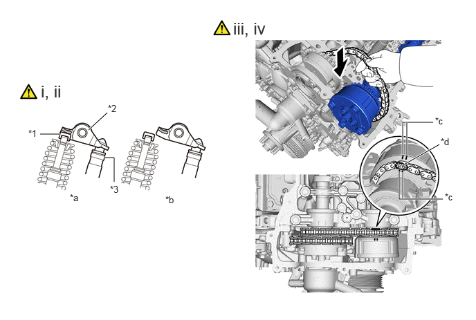
| *1 | Valve Stem Cap | *2 | No. 1 Valve Rocker Arm Sub-assembly |
| *3 | Valve Lash Adjuster Assembly | - | - |
| *a | CORRECT | *b | INCORRECT |
| *c | Timing Mark | *d | Mark Plate (Pink) |
Clean the camshaft housing LH and camshaft journals and apply engine oil to them.
Make sure that the No. 1 valve rocker arm sub-assembly is installed as shown in the illustration.
Align the mark plate (pink) with the timing mark of the camshaft timing exhaust gear assembly as shown in the illustration and install the No. 2 chain sub-assembly to the exhaust camshaft sub-assembly LH.
Set the exhaust camshaft sub-assembly LH to the camshaft housing LH.
6.INSTALL CAMSHAFT BEARING CAP (for Bank 2)
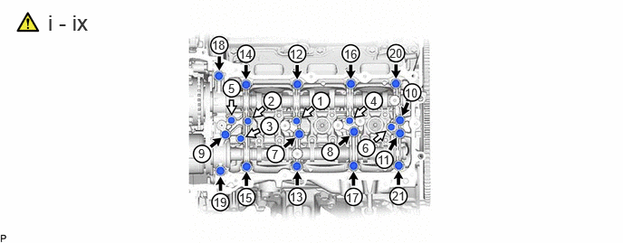

|
Bolt A |

|
Bolt B |
Clean the camshaft bearing caps and apply engine oil to them.
Remove the bolt and washer (No. 5 camshaft bearing cap side) used to temporarily install the camshaft housing.
- NOTICE:
-
Do not remove the bolt and washer for temporarily installing the camshaft housing other than those on the No. 5 camshaft bearing cap.
Temporarily install the No. 5 camshaft bearing cap.
- NOTICE:
-
Hold the chain plunger of the No. 3 chain tensioner assembly and insert the No. 5 camshaft bearing cap through the gap in the No. 3 chain tensioner assembly and No. 2 chain sub-assembly to install it.
Remove the bolt and washer (No. 8 camshaft bearing cap and No. 9 camshaft bearing cap sides) used to temporarily install the camshaft housing.
- NOTICE:
-
Do not remove the bolt and washer for temporarily installing the camshaft housing other than those on the No. 8 camshaft bearing cap and No. 9 camshaft bearing cap.
Temporarily install the No. 8 camshaft bearing cap, No. 9 camshaft bearing cap and fuel pump lifter housing LH.
Remove the bolt and washer (No. 7 camshaft bearing cap side) used to temporarily install the camshaft housing.
- NOTICE:
-
Do not remove the bolt and washer for temporarily installing the camshaft housing other than those on the No. 7 camshaft bearing cap.
Temporarily install the No. 6 camshaft bearing cap and No. 7 camshaft bearing cap.
Tighten the bearing caps and fuel pump lifter housing LH with the bolts in the order shown in the illustration.
- Torque:
- Bolt A : 28 N*m (286 kgf*cm, 21 ft.*lbf)
- Bolt B : 16 N*m (163 kgf*cm, 12 ft.*lbf)
- NOTICE:
-
·
Be sure to follow the numerical order when performing this procedure.
·Do not drop replacement bolts and washers into the cylinder head sub-assembly.
Check the torque of each bolt again.
13506A 7.CONNECT NO. 1 CHAIN SUB-ASSEMBLY (for Bank 2)
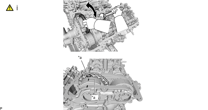
| *a | Paint Mark | - | - |
Align the paint marks on the camshaft timing gear assembly and No. 1 chain sub-assembly and install the No. 1 chain sub-assembly to the camshaft timing gear assembly.
- HINT:
-
If the paint marks are not aligned, align them by turning the camshaft slightly.
13540 8.INSTALL NO. 1 CHAIN TENSIONER ASSEMBLY (for Bank 2)
|
|
Click here() |
9.INSPECT VALVE TIMING
|
|
Click here() |
11324 10.INSTALL TIMING CHAIN COVER PLATE
11.SET NO. 1 CYLINDER TO TDC/COMPRESSION (for Bank 1)
|
|
Click here() |
13050B 12.INSTALL CAMSHAFT TIMING INTAKE GEAR ASSEMBLY RH (for Intake Side of Bank 1)
|
|
|
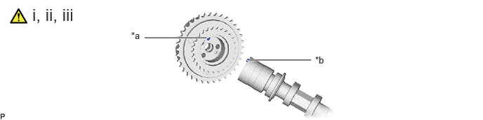
| *a | Pin Hole | *b | Straight Pin |
Put the camshaft timing intake gear assembly RH and intake camshaft sub-assembly RH together by aligning the pin hole and straight pin.
Temporarily install the camshaft timing oil control valve assembly (intake camshaft timing gear bolt assembly) to the camshaft timing intake gear assembly RH.
- NOTICE:
-
If the camshaft timing oil control valve assembly (intake camshaft timing gear bolt assembly) has been struck or dropped, replace it.
Temporarily install the 3 bolts.
| *a | Hexagonal Portion | - | - |
Using SST, grip the hexagonal portion, and then secure SST and intake camshaft sub-assembly RH in a vise as shown in the illustration.
- SST
-
09212-31010
- NOTICE:
-
·
Do not damage the intake camshaft sub-assembly RH.
·Never grip areas other than the hexagonal portion, as this may cause damage.
Using a 5 mm hexagon socket wrench, install the camshaft timing intake gear assembly RH with the 3 bolts and install the camshaft timing oil control valve assembly (intake camshaft timing gear bolt assembly).
- Torque:
- 19 N*m (194 kgf*cm, 14 ft.*lbf)
13501B 13.INSTALL INTAKE CAMSHAFT SUB-ASSEMBLY RH
|
|
|
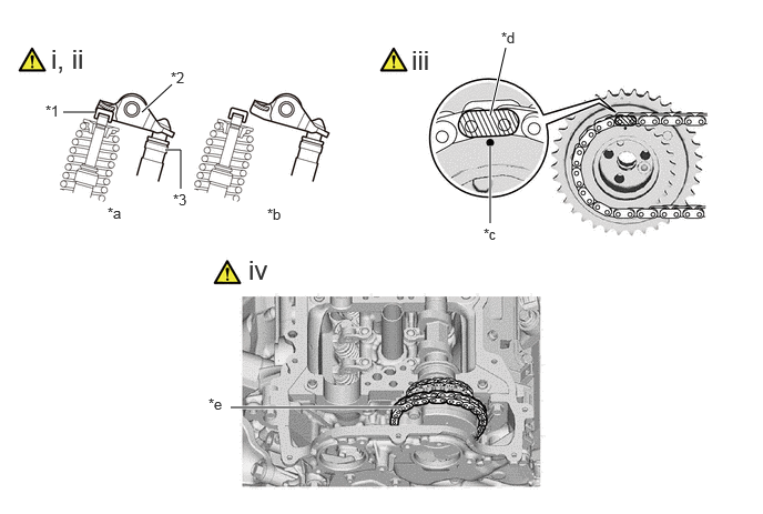
| *1 | Valve Stem Cap | *2 | No. 1 Valve Rocker Arm Sub-assembly |
| *3 | Valve Lash Adjuster Assembly | - | - |
| *a | CORRECT | *b | INCORRECT |
| *c | Timing Mark | *d | Mark Plate (Pink) |
| *e | Place on camshaft timing gear assembly | - | - |
Clean the camshaft housing RH and camshaft journals and apply engine oil to them.
Make sure that the No. 1 valve rocker arm sub-assembly is installed as shown in the illustration.
Align the mark plate (pink) with the timing mark of the camshaft timing gear assembly as shown in the illustration and install the No. 2 chain sub-assembly to the camshaft timing intake gear assembly RH.
Install the No. 1 chain sub-assembly to the camshaft timing gear assembly, and then set the camshaft timing gear assembly to the camshaft housing RH.
- HINT:
-
·
Place the No. 1 chain sub-assembly on the camshaft timing gear assembly but do not engage the teeth of the sprocket and the chain sub-assembly.
·Install the camshaft timing gear assembly so that the timing mark is facing upward.
13070 14.INSTALL CAMSHAFT TIMING EXHAUST GEAR ASSEMBLY RH (for Exhaust Side of Bank 1)
|
|
|
| *a | Pin Hole | *b | Straight Pin |
Put the camshaft timing exhaust gear assembly RH and exhaust camshaft sub-assembly RH together by aligning the pin hole and straight pin.
Temporarily install the camshaft timing oil control valve assembly (exhaust camshaft timing gear bolt assembly) to the camshaft timing exhaust gear assembly RH.
- NOTICE:
-
If the camshaft timing oil control valve assembly (exhaust camshaft timing gear bolt assembly) has been struck or dropped, replace it.
Temporarily install the 3 bolts.
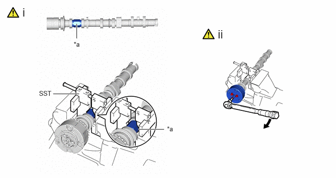
| *a | Hexagonal Portion | - | - |
Using SST, grip the hexagonal portion, and then secure SST and exhaust camshaft sub-assembly RH in a vise as shown in the illustration.
- SST
-
09212-31010
- NOTICE:
-
·
Do not damage the exhaust camshaft sub-assembly RH.
·Never grip areas other than the hexagonal portion, as this may cause damage.
Using a 5 mm hexagon socket wrench, install the camshaft timing exhaust gear assembly RH with the 3 bolts and install the camshaft timing oil control valve assembly (exhaust camshaft timing gear bolt assembly).
- Torque:
- 19 N*m (194 kgf*cm, 14 ft.*lbf)
13502C 15.INSTALL EXHAUST CAMSHAFT SUB-ASSEMBLY RH
|
|
|
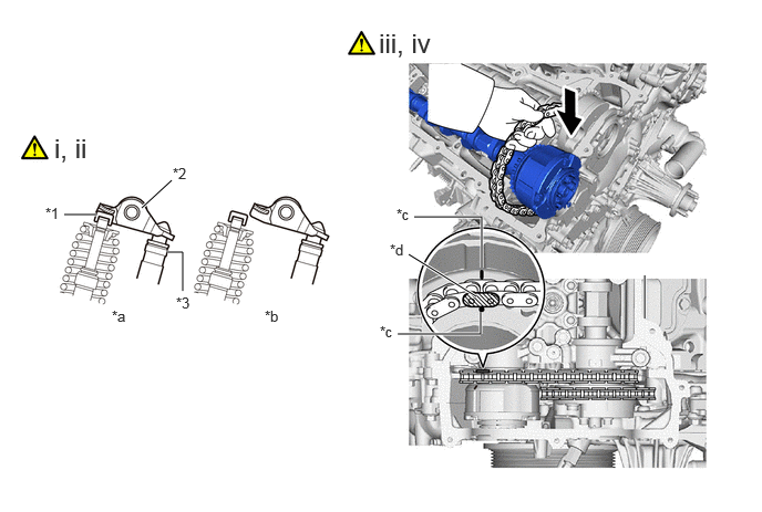
| *1 | Valve Stem Cap | *2 | No. 1 Valve Rocker Arm Sub-assembly |
| *3 | Valve Lash Adjuster Assembly | - | - |
| *a | CORRECT | *b | INCORRECT |
| *c | Timing Mark | *d | Mark Plate (Pink) |
Clean the camshaft housing RH and camshaft journals and apply engine oil to them.
Make sure that the No. 1 valve rocker arm sub-assembly is installed as shown in the illustration.
Align the mark plate (pink) with the timing mark of the camshaft timing exhaust gear assembly as shown in the illustration and install the No. 2 chain sub-assembly to the camshaft timing exhaust gear assembly.
Set the camshaft timing exhaust gear assembly RH to the camshaft housing RH.
16.INSTALL CAMSHAFT BEARING CAP (for Bank 1)
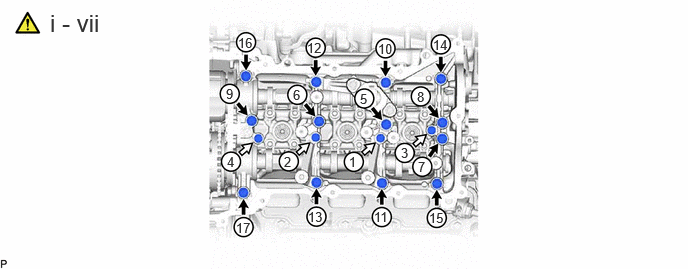
|
|
Bolt A |
|
Bolt B |
Clean the camshaft bearing caps and apply engine oil to them.
Remove the bolt and washer (No. 1 camshaft bearing cap side) used to temporarily install the camshaft housing.
- NOTICE:
-
Do not remove the bolt and washer for temporarily installing the camshaft housing other than those on the No. 1 camshaft bearing cap.
Temporarily install the No. 1 camshaft bearing cap.
- NOTICE:
-
Hold the chain plunger of the No. 2 chain tensioner assembly and insert the No. 1 camshaft bearing cap through the gap in the No. 2 chain tensioner assembly and No. 2 chain sub-assembly to install it.
Remove the bolt and washer (No. 3 camshaft bearing cap and No. 4 camshaft bearing cap sides) used to temporarily install the camshaft housing.
- NOTICE:
-
Do not remove the bolt and washer for temporarily installing the camshaft housing other than those on the No. 3 camshaft bearing cap and No. 4 camshaft bearing cap.
Temporarily install the No. 3 camshaft bearing cap, No. 4 camshaft bearing cap and fuel pump lifter housing RH.
Tighten the bearing caps and fuel pump lifter housing RH with the bolts in the order shown in the illustration.
- Torque:
- Bolt A : 28 N*m (286 kgf*cm, 21 ft.*lbf)
- Bolt B : 16 N*m (163 kgf*cm, 12 ft.*lbf)
- NOTICE:
-
·
Be sure to follow the numerical order when performing this procedure.
·Do not drop replacement bolts and washers into the cylinder head sub-assembly.
Check the torque of each bolt again.
13506A 17.CONNECT NO. 1 CHAIN SUB-ASSEMBLY (for Bank 1)
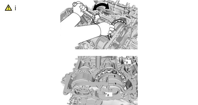
| *a | Paint Mark | - | - |
Align the paint marks on the camshaft timing gear assembly and chain sub-assembly and install the chain sub-assembly to the camshaft timing gear assembly.
- HINT:
-
If the paint marks are not aligned, align them by turning the camshaft slightly.
13540 18.INSTALL NO. 1 CHAIN TENSIONER ASSEMBLY (for Bank 1)
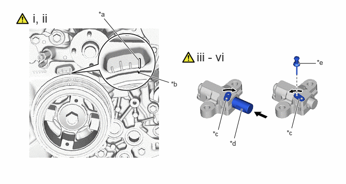
| *a | "0" Timing Mark | *b | Timing Mark (Cutout) |
| *c | Stopper Plate | *d | Plunger |
| *e | Pin | - | - |
Turn the crankshaft counterclockwise 30° past the "0" timing mark, and then turn it clockwise to align the notch with the "0" timing mark.
Turn the crankshaft slightly to eliminate the slack in the chain sub-assembly.
- HINT:
-
Make sure there is some slack in the chain around the area where the No. 1 chain tensioner assembly is installed.
While turning the stopper plate of the tensioner clockwise, push in the plunger of the No. 1 chain tensioner assembly as shown in the illustration.
While turning the stopper plate of the No. 1 chain tensioner assembly counterclockwise, insert a pin of 1.27 mm (0.0500 in.) into the holes in the stopper plate and No. 1 chain tensioner assembly to fix the stopper plate in place.
Install the No. 1 chain tensioner assembly with the 2 bolts.
- Torque:
- 21 N*m (214 kgf*cm, 15 ft.*lbf)
Remove the pin from the No. 1 chain tensioner assembly.
19.INSPECT VALVE TIMING
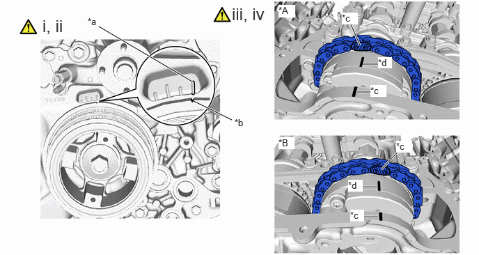
| *A | for Bank 2 | *B | for Bank 1 |
| *a | "0" Timing Mark | *b | Timing Mark (Cutout) |
| *c | Paint Mark | *d | Timing Mark (Groove) |
Turn the crankshaft until the timing mark (cutout) of the crankshaft pulley assembly and the "0" timing mark of the timing chain cover assembly are aligned.
Check the camshaft timing marks.
- NOTICE:
-
·
Check each timing mark from a viewpoint directly in line with the center of the camshaft and the timing mark on each camshaft timing gear assembly.
·If the timing marks are checked from any other viewpoint, the valve timing may appear misaligned.
Check that each camshaft timing mark is positioned as shown in the illustration.
If the valve timing is misaligned, reinstall the timing chain sub-assembly.
11324 20.INSTALL TIMING CHAIN COVER PLATE
- Torque:
- 10 N*m (102 kgf*cm, 7 ft.*lbf)
15370E 21.INSTALL CAM TIMING OIL CONTROL SOLENOID LH O-RING (for Exhaust Side of Bank 2)
|
|
Click here() |
15370C 22.INSTALL CAM TIMING OIL CONTROL SOLENOID ASSEMBLY LH (for Exhaust Side of Bank 2)
|
|
Click here() |
15370E 23.INSTALL CAM TIMING OIL CONTROL SOLENOID LH O-RING (for Intake Side of Bank 2)
|
|
Click here() |
15370C 24.INSTALL CAM TIMING OIL CONTROL SOLENOID ASSEMBLY LH (for Intake Side of Bank 2)
|
|
Click here() |
15370D 25.INSTALL CAM TIMING OIL CONTROL SOLENOID RH O-RING (for Exhaust Side of Bank 1)
|
|
Click here() |
15370B 26.INSTALL CAM TIMING OIL CONTROL SOLENOID ASSEMBLY RH (for Exhaust Side of Bank 1)
|
|
Click here() |
15370D 27.INSTALL CAM TIMING OIL CONTROL SOLENOID RH O-RING (for Intake Side of Bank 1)
|
|
Click here() |
15370B 28.INSTALL CAM TIMING OIL CONTROL SOLENOID ASSEMBLY RH (for Intake Side of Bank 1)
|
|
Click here() |
29.INSTALL WATER OUTLET PIPE WITH WATER BY-PASS JOINT
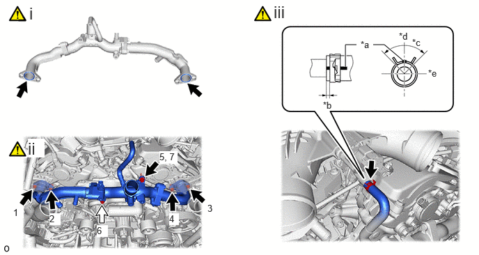
| *a | Paint Mark | *b | 1.0 to 7.0 mm (0.039 to 0.276 in.) |
| *c | 90° | *d | Upper Side |
| *e | LH Side | - | - |
|
|
Bolt A |
|
Bolt B |
Install 2 new gaskets to the water outlet pipe with water by-pass joint.
Tighten the 6 bolts in the order shown in the illustration.
- Torque:
- 21 N*m (214 kgf*cm, 15 ft.*lbf)
Connect the No. 9 water by-pass hose to the water outlet pipe with water by-pass joint and slide the clip to secure it.
- NOTICE:
-
·
Align the hose and the hose clip at the locations shown in the illustration and install them.
·Make sure the No. 9 water by-pass hose is securely inserted to the stopper.
30.INSTALL WATER INLET PIPE WITH WATER INLET HOSE
|
|
Click here() |
44310 31.CONNECT VANE PUMP ASSEMBLY
|
|
Click here() |
11193A 32.INSTALL SPARK PLUG TUBE GASKET LH
11202 33.INSTALL CYLINDER HEAD COVER SUB-ASSEMBLY LH
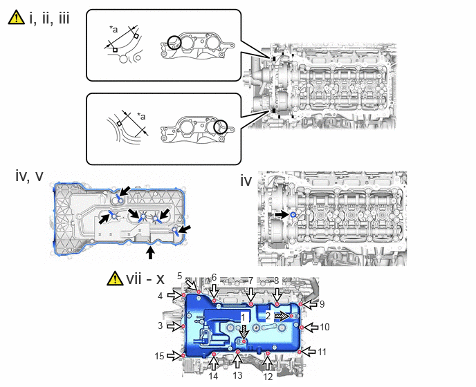
| *a | Application Range | - | - |
|
|
Bolt A |

|
Bolt B |
Before applying seal packing black, cleanly remove any old sealant sticking to the part to be sealed.
Remove any remaining seal packing material and be careful not to drop any oil on the contact surfaces of the cylinder head sub-assembly, timing chain cover assembly and cylinder head cover sub-assembly LH.
Apply seal packing as shown in the illustration.
- Seal packing:
-
Toyota Genuine Seal Packing Black, Three Bond 1207B or equivalent
- NOTICE:
-
·
Remove any oil from the contact surface.
·Install the cylinder head cover sub-assembly LH within 3 minutes and tighten the bolts within 15 minutes after applying seal packing.
- HINT:
-
Area Seal Packing Diameter Continuous Line Area 4.0 to 7.0 mm (0.157 to 0.276 in.) Diagonal Line 3.0 to 6.0 mm (0.118 to 0.236 in.)
Install a new No. 1 cylinder head cover gasket LH to the cylinder head cover sub-assembly LH.
Install 5 new No. 2 cylinder head cover gasket LH to the cylinder head cover sub-assembly LH.
Install a new camshaft bearing cap oil hole gasket LH to the camshaft bearing cap.
Degrease the threads of the 13 cylinder head cover installation bolts (A).
Temporarily install the 2 camshaft position sensors with 2 new bolts (B).
- NOTICE:
-
·
If the camshaft position sensor has been struck or dropped, replace it.
·Set the O-ring on the tip of the camshaft position sensor and roll it into the O-ring groove with bare hands to install it.
Click hereEngine / Hybrid System>V35A-FTS (ENGINE CONTROL)>CAMSHAFT POSITION SENSOR>INSTALLATION
Temporarily install the cylinder head cover sub-assembly LH with the 13 bolts (A).
Temporarily install the cylinder head cover sub-assembly LH with the 15 bolts. Tighten the bolts uniformly in several steps.
- Torque:
- 10 N*m (102 kgf*cm, 7 ft.*lbf)
- Bolt Length:
-
Item Length Bolt A 23.5 mm (0.925 in.) Bolt B 30 mm (1.18 in.)
- NOTICE:
-
Do not start the engine for at least 2 hours after installation.
11193B 34.INSTALL SPARK PLUG TUBE GASKET RH
11201M 35.INSTALL CYLINDER HEAD COVER SUB-ASSEMBLY RH
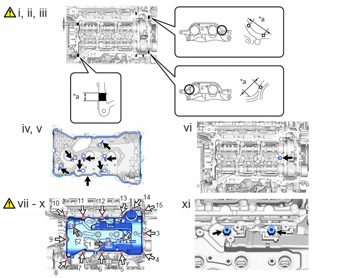
| *a | Application Range | - | - |
|
|
Bolt A |
|
Bolt B |
Before applying seal packing black, cleanly remove any old sealant sticking to the part to be sealed.
Remove any remaining seal packing material and be careful not to drop any oil on the contact surfaces of the cylinder head sub-assembly, timing chain cover assembly and cylinder head cover sub-assembly.
Apply seal packing as shown in the illustration.
- Seal packing:
-
Toyota Genuine Seal Packing Black, Three Bond 1207B or equivalent
- NOTICE:
-
·
Remove any oil from the contact surface.
·Install the cylinder head cover sub-assembly within 3 minutes and tighten the bolts within 15 minutes after applying seal packing.
- HINT:
-
Area Seal Packing Diameter Continuous Line Area 4.0 to 7.0 mm (0.157 to 0.276 in.) Diagonal Line 3.0 to 6.0 mm (0.118 to 0.236 in.)
Install a new No. 1 cylinder head cover gasket RH to the cylinder head cover sub-assembly RH.
Install 7 new No. 2 cylinder head cover gasket RH to the cylinder head cover sub-assembly RH.
Install a new camshaft bearing cap oil hole gasket RH to the camshaft bearing cap.
Degrease the threads of the 13 cylinder head cover installation bolts (A).
Temporarily install the 2 camshaft position sensors with 2 new bolts (B).
- NOTICE:
-
·
If the camshaft position sensor has been struck or dropped, replace it.
·Set the O-ring on the tip of the camshaft position sensor and roll it into the O-ring groove with bare hands to install it.
Click hereEngine / Hybrid System>V35A-FTS (ENGINE CONTROL)>CAMSHAFT POSITION SENSOR>INSTALLATION
Temporarily install the cylinder head cover sub-assembly RH with the 13 bolts (A).
Temporarily install the cylinder head cover sub-assembly with the 15 bolts. Tighten the bolts uniformly in several steps.
- Torque:
- 10 N*m (102 kgf*cm, 7 ft.*lbf)
- Bolt Length:
-
Item Length Bolt A 23.5 mm (0.925 in.) Bolt B 30 mm (1.18 in.)
- NOTICE:
-
Do not start the engine for at least 2 hours after installation.
Install the 2 No. 1 intercooler air guides to the cylinder head cover sub-assembly RH.
- Torque:
- 21 N*m (214 kgf*cm, 15 ft.*lbf)
36.INSTALL VACUUM HOSE
2382A 37.INSTALL NO. 4 FUEL VAPOR FEED HOSE
19500 38.INSTALL IGNITION COIL ASSEMBLY
|
|
Click here() |
39.INSTALL WIRE HARNESS CLAMP BRACKET
- Torque:
- 10 N*m (102 kgf*cm, 7 ft.*lbf)
16279 40.INSTALL NO. 3 WATER BY-PASS PIPE
- Torque:
- 21 N*m (214 kgf*cm, 15 ft.*lbf)
16027 41.CONNECT NO. 1 TURBO WATER PIPE SUB-ASSEMBLY
- Torque:
- 10 N*m (102 kgf*cm, 7 ft.*lbf)
82715X 42.INSTALL NO. 2 WIRING HARNESS CLAMP BRACKET
- Torque:
- 13 N*m (133 kgf*cm, 10 ft.*lbf)
43.CONNECT AIR FUEL RATIO SENSOR
23818 44.INSTALL FUEL VAPOR FEED PIPE
- Torque:
- 10 N*m (102 kgf*cm, 7 ft.*lbf)
17650G 45.INSTALL PURGE VSV
11452 46.INSTALL ENGINE OIL LEVEL DIPSTICK GUIDE
47.INSTALL INTERCOOLER COOLING WATER PIPE ASSEMBLY AND TURBO WATER HOSE
- Torque:
- 10 N*m (102 kgf*cm, 7 ft.*lbf)
23804J 48.INSTALL FUEL INLET PIPE SUB-ASSEMBLY
- Torque:
- 10 N*m (102 kgf*cm, 7 ft.*lbf)
11256 49.INSTALL NO. 2 V-BANK COVER BRACKET
- Torque:
- 10 N*m (102 kgf*cm, 7 ft.*lbf)
1628A 50.INSTALL NO. 6 WATER BY-PASS PIPE
- Torque:
- 10 N*m (102 kgf*cm, 7 ft.*lbf)
16289 51.INSTALL NO. 5 WATER BY-PASS PIPE
17312D 52.INSTALL NO. 2 AIR INLET DUCT
- Torque:
- for bolt : 10 N*m (102 kgf*cm, 7 ft.*lbf)
- for hose clamp : 4.0 N*m (41 kgf*cm, 35 in.*lbf)
23901 53.INSTALL FUEL TUBE SUB-ASSEMBLY
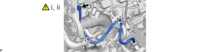
Connect the fuel tube sub-assembly.
Click hereEngine / Hybrid System>V35A-FTS (FUEL)>FUEL SYSTEM>PRECAUTION
Attach the 2 clamps and install the fuel tube sub-assembly.
17311 54.INSTALL NO. 1 AIR INLET DUCT
- Torque:
- for bolt : 10 N*m (102 kgf*cm, 7 ft.*lbf)
- for hose clamp : 4.0 N*m (41 kgf*cm, 35 in.*lbf)
12262 55.INSTALL NO. 2 PCV HOSE
23901 56.CONNECT FUEL TUBE SUB-ASSEMBLY
|
|
Click here() |
23826 57.CONNECT NO. 1 FUEL VAPOR FEED HOSE
58.CONNECT HEATER WATER HOSE OUTLET A
87209 59.CONNECT WATER HOSE SUB-ASSEMBLY
|
|
Click here() |
162A0 60.CONNECT NO. 4 WATER BY-PASS HOSE ASSEMBLY
|
|
Click here() |
16267C 61.CONNECT NO. 4 WATER BY-PASS HOSE
16572D 62.CONNECT NO. 2 RADIATOR HOSE
|
|
Click here() |
74410 63.INSTALL BATTERY CARRIER ASSEMBLY
28800 64.INSTALL BATTERY
51448M 65.INSTALL ENGINE SIDE UNDER COVER RH
51478C 66.INSTALL UPPER ENGINE SIDE UNDER COVER PLATE LH
51470C 67.INSTALL REAR ENGINE SIDE UNDER COVER ASSEMBLY LH
53785B 68.INSTALL FRONT FENDER APRON TRIM PACKING D
53784 69.INSTALL FRONT FENDER APRON TRIM PACKING C
53783 70.INSTALL FRONT FENDER APRON TRIM PACKING B
53782 71.INSTALL FRONT FENDER APRON TRIM PACKING A
72.INSTALL FRONT WHEEL
16711 73.INSTALL FAN SHROUD
23100X 74.INSTALL FUEL (ENGINE ROOM SIDE) PUMP ASSEMBLY
75.INSPECT IGNITION TIMING