SUSPENSION CONTROL ADAPTIVE VARIABLE SUSPENSION SYSTEM C1731 Front Damping Force Control Actuator RH Circuit Malfunction C1732 Front Damping Force Control Actuator LH Circuit Malfunction C1733 Rear Damping Force Control Actuator RH Circuit Malfunction C1734 Rear Damping Force Control Actuator LH Circuit Malfunction
DESCRIPTION
The absorber control actuator changes the damping force depending on absorber control ECU signals.
| DTC No. | Detection Item | DTC Detection Condition | Trouble Area | Warning Indicate | Memory |
|---|---|---|---|---|---|
| C1731 | Front Damping Force Control Actuator RH Circuit Malfunction | Either condition is met:
·
An open circuit is detected between the front absorber control actuator RH (front shock absorber assembly RH) and absorber control ECU.
·
A short circuit is detected between the front absorber control actuator RH (front shock absorber assembly RH) and absorber control ECU. |
·
Front absorber control actuator RH (front shock absorber assembly RH)
·
Absorber control wire RH (front speed sensor RH)
·
Wire harness or connector
·
Absorber control ECU |
Does not come on | Yes |
| C1732 | Front Damping Force Control Actuator LH Circuit Malfunction | Either condition is met:
·
An open circuit is detected between the front absorber control actuator LH (front shock absorber assembly LH) and absorber control ECU.
·
A short circuit is detected between the front absorber control actuator LH (front shock absorber assembly LH) and absorber control ECU. |
·
Front absorber control actuator LH (front shock absorber assembly LH)
·
Absorber control wire LH (front speed sensor LH)
·
Wire harness or connector
·
Absorber control ECU |
Does not come on | Yes |
| C1733 | Rear Damping Force Control Actuator RH Circuit Malfunction | Either condition is met:
·
An open circuit is detected between the rear absorber control actuator RH (rear shock absorber assembly RH) and absorber control ECU.
·
A short circuit is detected between the rear absorber control actuator RH (rear shock absorber assembly RH) and absorber control ECU. |
·
Rear absorber control actuator RH (rear shock absorber assembly RH)
·
No. 1 parking brake wire assembly
·
Wire harness or connector
·
Absorber control ECU |
Does not come on | Yes |
| C1734 | Rear Damping Force Control Actuator LH Circuit Malfunction | Either condition is met:
·
An open circuit is detected between the rear absorber control actuator LH (rear shock absorber assembly LH) and absorber control ECU.
·
A short circuit is detected between the rear absorber control actuator LH (rear shock absorber assembly LH) and absorber control ECU. |
·
Rear absorber control actuator LH (rear shock absorber assembly LH)
·
No. 2 parking brake wire assembly
·
Wire harness or connector
·
Absorber control ECU |
Does not come on | Yes |
| Vehicle Condition | |||
|---|---|---|---|
| Pattern 1 | Pattern 2 | ||
| Diagnosis Condition | Ignition switch is ON | ○ | ○ |
| Malfunction Status | An open circuit is detected between the front absorber control actuator RH (front shock absorber assembly RH) and absorber control ECU | ○ | - |
| A short circuit is detected between the front absorber control actuator RH (front shock absorber assembly RH) and absorber control ECU | - | ○ | |
| Detection Time | - | - | |
| Number of Trips | 1 trip | 1 trip | |
- HINT:
-
DTC will be output when conditions for either of the patterns in the table above are met.
| Vehicle Condition | |||
|---|---|---|---|
| Pattern 1 | Pattern 2 | ||
| Diagnosis Condition | Ignition switch is ON | ○ | ○ |
| Malfunction Status | An open circuit is detected between the front absorber control actuator LH (front shock absorber assembly LH) and absorber control ECU | ○ | - |
| A short circuit is detected between the front absorber control actuator LH (front shock absorber assembly LH) and absorber control ECU | - | ○ | |
| Detection Time | - | - | |
| Number of Trips | 1 trip | 1 trip | |
- HINT:
-
DTC will be output when conditions for either of the patterns in the table above are met.
| Vehicle Condition | |||
|---|---|---|---|
| Pattern 1 | Pattern 2 | ||
| Diagnosis Condition | Ignition switch is ON | ○ | ○ |
| Malfunction Status | An open circuit is detected between the rear absorber control actuator RH (rear shock absorber assembly RH) and absorber control ECU | ○ | - |
| A short circuit is detected between the rear absorber control actuator RH (rear shock absorber assembly RH) and absorber control ECU | - | ○ | |
| Detection Time | - | - | |
| Number of Trips | 1 trip | 1 trip | |
- HINT:
-
DTC will be output when conditions for either of the patterns in the table above are met.
| Vehicle Condition | |||
|---|---|---|---|
| Pattern 1 | Pattern 2 | ||
| Diagnosis Condition | Ignition switch is ON | ○ | ○ |
| Malfunction Status | An open circuit is detected between the rear absorber control actuator LH (rear shock absorber assembly LH) and absorber control ECU | ○ | - |
| A short circuit is detected between the rear absorber control actuator LH (rear shock absorber assembly LH) and absorber control ECU | - | ○ | |
| Detection Time | - | - | |
| Number of Trips | 1 trip | 1 trip | |
- HINT:
-
DTC will be output when conditions for either of the patterns in the table above are met.
WIRING DIAGRAM
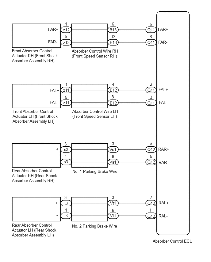
CAUTION / NOTICE / HINT
- NOTICE:
-
·
Before performing troubleshooting, inspect the connectors of related circuits.
·If DTC C1782 (Power Source Voltage Malfunction) is output at the same time, perform troubleshooting for C1782 first.
Click hereSuspension>SUSPENSION CONTROL>ADAPTIVE VARIABLE SUSPENSION SYSTEM>C1782
·Before replacing the absorber control ECU, perform all of the following:
-Symptom simulation.
Click hereGeneral>INTRODUCTION>HOW TO TROUBLESHOOT ECU CONTROLLED SYSTEMS>HOW TO PROCEED WITH TROUBLESHOOTING
-DTC inspection.
-GTS inspection.
Click hereSuspension>SUSPENSION CONTROL>ADAPTIVE VARIABLE SUSPENSION SYSTEM>DATA LIST / ACTIVE TEST
*If no malfunctions are found in other areas, replace the absorber control ECU.
·After replacing the absorber control ECU with a new one, perform registration of vehicle identification information.
Click hereSuspension>SUSPENSION CONTROL>ADAPTIVE VARIABLE SUSPENSION SYSTEM>TEST MODE PROCEDURE
PROCEDURE
Clear the DTCs.
- Chassis > Adaptive Variable Suspension System > Clear DTCs
- 50002 171
- Result:
-
Proceed to NEXT
NEXT
Start the engine.
When performing the Active Test, read each Tester Display item for the applicable wheel on the Data List and check the operation status of the absorber control actuator for the applicable wheel.
- Chassis > Adaptive Variable Suspension System > Active Test
-
Tester Display Measurement Item Restrict Condition Four-Wheel Damping Force Full Hard Four-Wheel Damping Force Full Hard ·Vehicle stopped
·Engine idling
·When the actuator system is normal
·When the power source voltage system is normal
Four-Wheel Damping Force Full Soft Four-Wheel Damping Force Full Soft ·Vehicle stopped
·Engine idling
·When the actuator system is normal
·When the power source voltage system is normal
- Chassis > Adaptive Variable Suspension System > Data List
-
Tester Display Measurement Item Range Normal Condition Diagnostic Note FR Solenoid Aim Electric Current Level for Control Target solenoid current value (front wheel RH) Min.: 0 mA
Max.: 2040 mAChanges depending on step count - FL Solenoid Aim Electric Current Level for Control Target solenoid current value (front wheel LH) Min.: 0 mA
Max.: 2040 mAChanges depending on step count - RR Solenoid Aim Electric Current Level for Control Target solenoid current value (rear wheel RH) Min.: 0 mA
Max.: 2040 mAChanges depending on step count - RL Solenoid Aim Electric Current Level for Control Target solenoid current value (rear wheel LH) Min.: 0 mA
Max.: 2040 mAChanges depending on step count - FR Solenoid Drive Duty Solenoid drive duty value (front wheel RH) Min.: 0%
Max.: 100%Changes depending on step count - FL Solenoid Drive Duty Solenoid drive duty value (front wheel LH) Min.: 0%
Max.: 100%Changes depending on step count - RR Solenoid Drive Duty Solenoid drive duty value (rear wheel RH) Min.: 0%
Max.: 100%Changes depending on step count - RL Solenoid Drive Duty Solenoid drive duty value (rear wheel LH) Min.: 0%
Max.: 100%Changes depending on step count - FR Solenoid Electric Current Solenoid current value (front wheel RH) Min.: 0 mA
Max.: 2040 mAChanges depending on step count - FL Solenoid Electric Current Solenoid current value (front wheel LH) Min.: 0 mA
Max.: 2040 mAChanges depending on step count - RR Solenoid Electric Current Solenoid current value (rear wheel RH) Min.: 0 mA
Max.: 2040 mAChanges depending on step count - RL Solenoid Electric Current Solenoid current value (rear wheel LH) Min.: 0 mA
Max.: 2040 mAChanges depending on step count -
- Chassis > Adaptive Variable Suspension System > Active Test
-
Active Test Display Four-Wheel Damping Force Full Hard -
Data List Display FR Solenoid Aim Electric Current Level for Control FL Solenoid Aim Electric Current Level for Control RR Solenoid Aim Electric Current Level for Control RL Solenoid Aim Electric Current Level for Control FR Solenoid Drive Duty FL Solenoid Drive Duty RR Solenoid Drive Duty RL Solenoid Drive Duty FR Solenoid Electric Current FL Solenoid Electric Current RR Solenoid Electric Current RL Solenoid Electric Current - 50004 171 75 114,115,116,117,118,119,120,121,122,123,124,125
- Chassis > Adaptive Variable Suspension System > Active Test
-
Active Test Display Four-Wheel Damping Force Full Soft -
Data List Display FR Solenoid Aim Electric Current Level for Control FL Solenoid Aim Electric Current Level for Control RR Solenoid Aim Electric Current Level for Control RL Solenoid Aim Electric Current Level for Control FR Solenoid Drive Duty FL Solenoid Drive Duty RR Solenoid Drive Duty RL Solenoid Drive Duty FR Solenoid Electric Current FL Solenoid Electric Current RR Solenoid Electric Current RL Solenoid Electric Current - 50004 171 76 114,115,116,117,118,119,120,121,122,123,124,125
- OK:
-
The Data List step numbers, drive duty values and current values change according to the operation of the Active Test.
- Result:
-
Proceed to OK NG
OK
NG
Check that the same DTC is output.
- Chassis > Adaptive Variable Suspension System > Trouble Codes
- 50001 171
- Result:
-
Result Proceed to DTC is output A DTC is not output B
A
B
Click hereGeneral>INTRODUCTION>HOW TO TROUBLESHOOT ECU CONTROLLED SYSTEMS>HOW TO PROCEED WITH TROUBLESHOOTING
Turn the ignition switch off.
Inspect the absorber control actuator (shock absorber assembly).
for Front Side: Click hereSuspension>SUSPENSION CONTROL>ABSORBER CONTROL ACTUATOR (for Front Side)>ON-VEHICLE INSPECTION
for Rear Side: Click hereSuspension>SUSPENSION CONTROL>ABSORBER CONTROL ACTUATOR (for Rear Side)>ON-VEHICLE INSPECTION
- Result:
-
Result Proceed to OK (for Front Side) A OK (for Rear Side) B Front absorber control actuator RH (front shock absorber assembly RH) malfunction C Front absorber control actuator LH (front shock absorber assembly LH) malfunction D Rear absorber control actuator RH (rear shock absorber assembly RH) malfunction E Rear absorber control actuator LH (rear shock absorber assembly LH) malfunction F
A
B
C
D
E
F
Turn the ignition switch off.
Disconnect the B13 or B12 absorber control wire (front speed sensor) connector.
Disconnect the z12 or z11 absorber control wire (front speed sensor) connector.
Measure the resistance according to the value(s) in the table below.
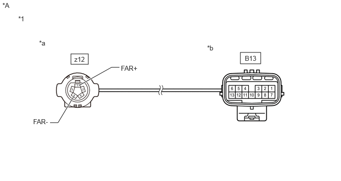
| *A | for RH | - | - |
| *1 | Absorber Control Wire (Front Speed Sensor) |
- | - |
| *a | Front view of wire harness connector (to Front Absorber Control Actuator Side Connector) |
*b | Front view of wire harness connector (to Vehicle Side Connector) |
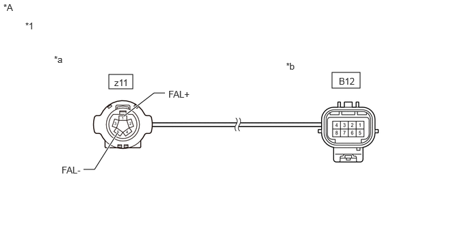
| *A | for LH | - | - |
| *1 | Absorber Control Wire (Front Speed Sensor) |
- | - |
| *a | Front view of wire harness connector (to Front Absorber Control Actuator Side Connector) |
*b | Front view of wire harness connector (to Vehicle Side Connector) |
- Standard Resistance:
-
for RH Tester Connection Condition Specified Condition Click Location & Routing(B13,z12)Location & Routingewd_type=routing;type=c,c;code=B13,z12
Click Connector(z12)Engine Compartment>other>Front Shock Absorber Assembly RH , Front Speed Sensor Wire RHewd_type=component;type=c;code=z12;pinno=5,1
B13-13 - z12-5 (FAR-) Always Below 1 Ω B13-6 - z12-1 (FAR+) B13-13 or z12-5 (FAR-) - Body ground and other terminals Always 10 kΩ or higher B13-6 or z12-1 (FAR+) - Body ground and other terminals
- Standard Resistance:
-
for LH Tester Connection Condition Specified Condition Click Location & Routing(B12,z11)Location & Routingewd_type=routing;type=c,c;code=B12,z11
Click Connector(z11)Engine Compartment>other>Front Shock Absorber Assembly LH , Front Speed Sensor Wire LHewd_type=component;type=c;code=z11;pinno=5,1
B12-8 - z11-5 (FAL-) Always Below 1 Ω B12-4 - z11-1 (FAL+) B12-8 or z11-5 (FAL-) - Body ground and other terminals Always 10 kΩ or higher B12-4 or z11-1 (FAL+) - Body ground and other terminals
- Result:
-
Proceed to OK NG
OK
NG
Turn the ignition switch off.
Disconnect the Q11 absorber control ECU connector.
Connect the B13 or B12 absorber control wire (front speed sensor) connector.
Measure the resistance according to the value(s) in the table below.
- Standard Resistance:
-
for Front RH Tester Connection Condition Specified Condition Click Location & Routing(Q11,z12)Location & Routingewd_type=routing;type=c,c;code=Q11,z12
Click Connector(z12)Engine Compartment>other>Front Shock Absorber Assembly RH , Front Speed Sensor Wire RHewd_type=component;type=c;code=z12;pinno=1,5
Q11-5 (FAR+) - z12-1 (FAR+) Always Below 1 Ω Q11-6 (FAR-) - z12-5 (FAR-) Q11-5 (FAR+) or z12-1 (FAR+) - Body ground Always 10 kΩ or higher Q11-6 (FAR-) or z12-5 (FAR-) - Body ground
-
for Front LH Tester Connection Condition Specified Condition Click Location & Routing(Q11,z11)Location & Routingewd_type=routing;type=c,c;code=Q11,z11
Click Connector(z11)Engine Compartment>other>Front Shock Absorber Assembly LH , Front Speed Sensor Wire LHewd_type=component;type=c;code=z11;pinno=1,5
Q11-2 (FAL+) - z11-1 (FAL+) Always Below 1 Ω Q11-3 (FAL-) - z11-5 (FAL-) Q11-2 (FAL+) or z11-1 (FAL+) - Body ground Always 10 kΩ or higher Q11-3 (FAL-) or z11-5 (FAL-) - Body ground
- Result:
-
Proceed to OK NG
OK
NG
Turn the ignition switch off.
Disconnect the Vs1 or Vt1 parking brake wire assembly connector.
Disconnect the s3 or t3 parking brake wire assembly connector.
Measure the resistance according to the value(s) in the table below.
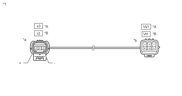
| *A | for RH | *B | for LH |
| *1 | Parking Brake Wire Assembly | - | - |
| *a | Front view of wire harness connector (to Rear Absorber Control Actuator Side Connector) |
*b | Front view of wire harness connector (to Vehicle Side Connector) |
- Standard Resistance:
-
for RH Tester Connection Condition Specified Condition Click Location & Routing(Vs1,s3)Location & Routingewd_type=routing;type=w,c;code=Vs1,s3
Click Connector(Vs1)Body>Differential Wire / Frame Wire>Frame Wire and No. 1 Parking Brake Wire Assemblyewd_type=component;type=w;code=Vs1;pinno=3,6
Click Connector(s3)Body>No. 1 Parking Brake Wire Assembly>Rear Shock Absorber Assembly RHewd_type=component;type=c;code=s3;pinno=3,1
Vs1-3 - s3-3 (+) Always Below 1 Ω Vs1-6 - s3-1 (-) Vs1-3 or s3-3 (+) - Body ground and other terminals Always 10 kΩ or higher Vs1-6 or s3-1 (-) - Body ground and other terminals
- Standard Resistance:
-
for LH Tester Connection Condition Specified Condition Click Location & Routing(Vt1,t3)Location & Routingewd_type=routing;type=w,c;code=Vt1,t3
Click Connector(Vt1)Body>Differential Wire / Frame Wire>Frame Wire and No. 2 Parking Brake Wire Assemblyewd_type=component;type=w;code=Vt1;pinno=3,6
Click Connector(t3)Body>No. 2 Parking Brake Wire Assembly>Rear Shock Absorber Assembly LHewd_type=component;type=c;code=t3;pinno=3,1
Vt1-3 - t3-3 (+) Always Below 1 Ω Vt1-6 - t3-1 (-) Vt1-3 or t3-3 (+) - Body ground and other terminals Always 10 kΩ or higher Vt1-6 or t3-1 (-) - Body ground and other terminals
- Result:
-
Proceed to OK NG
OK
NG
Turn the ignition switch off.
Disconnect the Q12 absorber control ECU connector.
Connect the Vs1 or Vt1 parking brake wire assembly connector.
Measure the resistance according to the value(s) in the table below.
- Standard Resistance:
-
for Rear RH Tester Connection Condition Specified Condition Click Location & Routing(Q12,s3)Location & Routingewd_type=routing;type=c,c;code=Q12,s3
Click Connector(s3)Body>No. 1 Parking Brake Wire Assembly>Rear Shock Absorber Assembly RHewd_type=component;type=c;code=s3;pinno=3,1
Q12-6 (RAR+) - s3-3 (+) Always Below 1 Ω Q12-5 (RAR-) - s3-1 (-) Q12-6 (RAR+) or s3-3 (+) - Body ground Always 10 kΩ or higher Q12-5 (RAR-) or s3-1 (-) - Body ground
-
for Rear LH Tester Connection Condition Specified Condition Click Location & Routing(Q12,t3)Location & Routingewd_type=routing;type=c,c;code=Q12,t3
Click Connector(t3)Body>No. 2 Parking Brake Wire Assembly>Rear Shock Absorber Assembly LHewd_type=component;type=c;code=t3;pinno=3,1
Q12-2 (RAL+) - t3-3 (+) Always Below 1 Ω Q12-1 (RAL-) - t3-1 (-) Q12-2 (RAL+) or t3-3 (+) - Body ground Always 10 kΩ or higher Q12-1 (RAL-) or t3-1 (-) - Body ground
- Result:
-
Proceed to OK NG
OK
NG