1GR-FE ENGINE MECHANICAL ENGINE UNIT REMOVAL
CAUTION / NOTICE / HINT
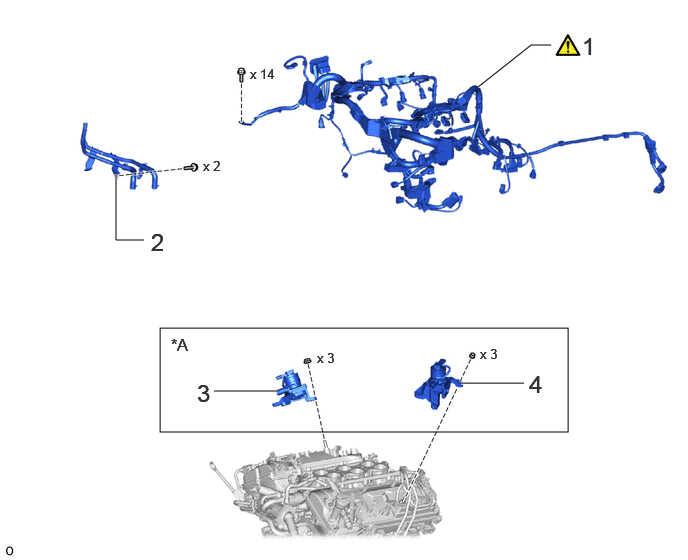
| Procedure | Part Name Code |

|

|

|
|
|---|---|---|---|---|---|
| 1 | ENGINE WIRE | 82121 | ( ) |
- | - |
| 2 | HEATER WATER HOSE ASSEMBLY | - | - | - | - |
| 3 | NO. 1 EMISSION CONTROL VALVE SET | 25701B | - | - | - |
| 4 | NO. 2 EMISSION CONTROL VALVE SET | 25702B | - | - | - |
| *A | w/ Secondary Air Injection System | - | - |
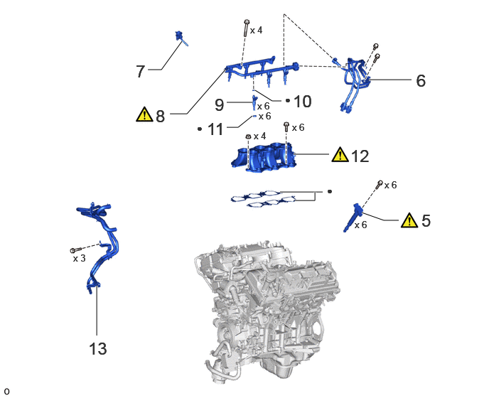
| Procedure | Part Name Code |
|
|
|
|
|---|---|---|---|---|---|
| 5 | IGNITION COIL ASSEMBLY | 19500 | () |
- | - |
| 6 | FUEL PIPE SUB-ASSEMBLY | - | - | - | - |
| 7 | VACUUM TRANSMITTING HOSE ASSEMBLY | 25760 | - | - | - |
| 8 | FUEL DELIVERY PIPE SUB-ASSEMBLY | 23807 | () |
- | - |
| 9 | FUEL INJECTOR ASSEMBLY | 23250 | - | - | - |
| 10 | FUEL INJECTOR O-RING | 23250B | - | - | - |
| 11 | INJECTOR VIBRATION INSULATOR | 23291 | - | - | - |
| 12 | INTAKE MANIFOLD | 17111 | () |
- | - |
| 13 | WATER BY-PASS PIPE SUB-ASSEMBLY | 16206 | - | - | - |
| ● | Non-reusable part | - | - |
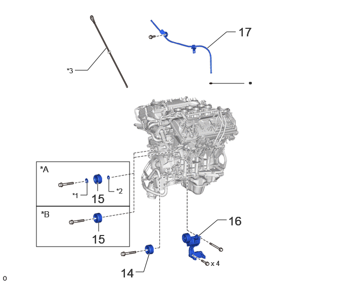
| Procedure | Part Name Code |
|
|
|
|
|---|---|---|---|---|---|
| 14 | NO. 1 IDLER PULLEY SUB-ASSEMBLY | 16603 | - | - | - |
| 15 | NO. 2 IDLER PULLEY SUB-ASSEMBLY | 16604 | - | - | - |
| 16 | V-RIBBED BELT TENSIONER ASSEMBLY | 16620 | - | - | - |
| 17 | ENGINE OIL LEVEL DIPSTICK GUIDE | 11452 | - | - | - |
| *A | for Separate Type | *B | for Integrated Type |
| *1 | NO. 2 IDLER PULLEY COVER PLATE | *2 | IDLER PULLEY COVER PLATE |
| *3 | ENGINE OIL LEVEL DIPSTICK | - | - |
| ● | Non-reusable part | - | - |
CAUTION / NOTICE / HINT
The necessary procedures (adjustment, calibration, initialization, or registration) that must be performed after parts are removed, installed, or replaced during the engine unit removal/installation are shown below.
| Replaced Part or Performed Procedure | Necessary Procedure | Effect/Inoperative Function when Necessary Procedure not Performed | Link |
|---|---|---|---|
| Battery terminal is disconnected/reconnected | Memorize steering angle neutral point | Parking assist monitor system | () |
| Multi-terrain monitor system | () |
||
| Panoramic view monitor system | () |
||
| Automatic transmission assembly | Reset memory |
·
Large shift shock
·
Engine overruns |
() |
| Automatic transmission fluid | ATF thermal degradation estimate reset | The value of the Data List item "ATF Thermal Degradation Estimate" is not estimated correctly. | |
|
·
Throttle body with motor assembly
·
Cleaning the deposits from the throttle body with motor assembly
·
Cylinder head sub-assembly
·
Camshaft (for intake or exhaust camshaft)
·
Camshaft timing gear assembly
·
Piston or piston ring
·
Fuel injector assembly
·
Fuel pump
·
Air fuel ratio sensor
·
Engine coolant temperature sensor
·
Spark plug
·
Ignition coil assembly
·
Air leaks from intake system
·
Gas leaks from exhaust system
·
Knock control sensor |
Inspection after repairs |
·
Poor idle, etc.
·
Engine start function, etc. |
() |
| Engine assembly | Inspection after repair |
·
Poor idle, etc.
·
Engine start function, etc. |
() |
| Front bumper assembly (Including removal and installation) | Front television camera view adjustment | Panoramic view monitor system | () |
- HINT:
-
When the cable is disconnected/reconnected to the battery terminal, systems temporarily stop operating. However, each system has a function that completes learning the first time the system is used.
-
·
Learning completes when vehicle is driven
Effect/Inoperative Function When Necessary Procedures are not Performed Necessary Procedures Link Lighting system (EXT) Cornering lights Drive the vehicle straight ahead at 35 km/h (22 mph) or more for 5 seconds or more. ( )Pre-collision system Lane tracing assist system Lane departure alert system Adaptive high beam system
·Learning completes when vehicle is operated normally
Effect/Inoperative Function When Necessary Procedures are not Performed Necessary Procedures Link Power back door system Fully close the back door by hand.
- HINT:
-
Initialization is not necessary if the above procedures are performed while the back door is closed.
( )Air conditioning system After the ignition switch is turned to ON, the servo motor and expansion valve standard position is recognized. -
PROCEDURE

 82121 1.REMOVE ENGINE WIRE
|
|
|
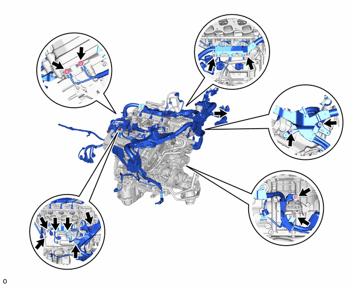
Remove the 14 bolts and disconnect the engine wire.
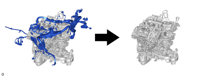
Remove the engine wire from the engine.
2.DISCONNECT HEATER WATER HOSE ASSEMBLY
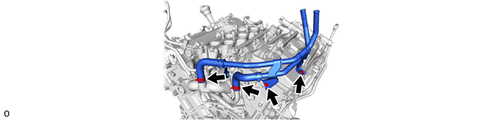
25701B 3.REMOVE NO. 1 EMISSION CONTROL VALVE SET (w/ Secondary Air Injection System)
25702B 4.REMOVE NO. 2 EMISSION CONTROL VALVE SET (w/ Secondary Air Injection System)
19500 5.REMOVE IGNITION COIL ASSEMBLY
|
|
Click here() |
6.REMOVE FUEL PIPE SUB-ASSEMBLY
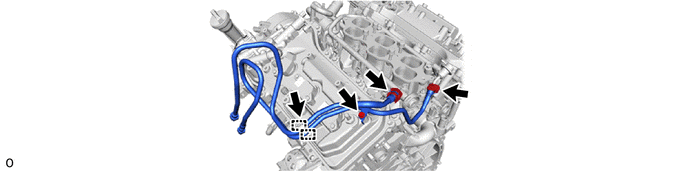
Disconnect the 2 fuel pipes.
Click hereEngine / Hybrid System>1GR-FE (FUEL)>FUEL SYSTEM>PRECAUTION
Remove the 2 bolts and No. 1 and No. 2 fuel pipes.
25760 7.DISCONNECT VACUUM TRANSMITTING HOSE ASSEMBLY
23807 8.REMOVE FUEL DELIVERY PIPE SUB-ASSEMBLY
|
|
Click here() |
23250 9.REMOVE FUEL INJECTOR ASSEMBLY
23250B 10.REMOVE FUEL INJECTOR O-RING
23291 11.REMOVE INJECTOR VIBRATION INSULATOR
17111 12.REMOVE INTAKE MANIFOLD
|
|
Click here() |
16206 13.REMOVE WATER BY-PASS PIPE SUB-ASSEMBLY
16603 14.REMOVE NO. 1 IDLER PULLEY SUB-ASSEMBLY
16604 15.REMOVE NO. 2 IDLER PULLEY SUB-ASSEMBLY
16620 16.REMOVE V-RIBBED BELT TENSIONER ASSEMBLY
11452 17.REMOVE ENGINE OIL LEVEL DIPSTICK GUIDE