1GR-FE LUBRICATION ENGINE OIL COOLER INSTALLATION
CAUTION / NOTICE / HINT
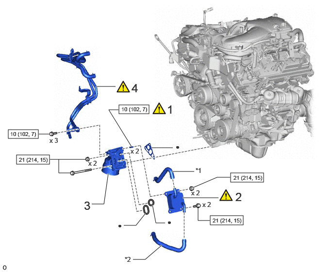
| Procedure | Part Name Code |

|

|

|
|
|---|---|---|---|---|---|
| 1 | STUD BOLT | - | ( ) |
- | - |
| 2 | OIL COOLER ASSEMBLY | 15710 | () |
- | - |
| 3 | OIL FILTER BRACKET | 15671 | - | - | - |
| 4 | WATER BY-PASS PIPE SUB-ASSEMBLY | 16206 | () |
- | - |
| *1 | NO. 8 WATER BY-PASS HOSE | *2 | NO. 9 WATER BY-PASS HOSE |

|
N*m (kgf*cm, ft.*lbf): Specified torque | ● | Non-reusable part |
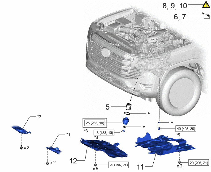
| Procedure | Part Name Code |
|
|
|
|
|---|---|---|---|---|---|
| 5 | OIL FILTER ELEMENT | - | - | - | - |
| 6 | ADD ENGINE OIL | - | - | () |
- |
| 7 | ADD ENGINE COOLANT | - | - | () |
- |
| 8 | INSPECT ENGINE OIL LEVEL | - | () |
- | - |
| 9 | INSPECT FOR OIL LEAK | - | () |
- | - |
| 10 | INSPECT FOR COOLANT LEAK | - | () |
- | - |
| 11 | NO. 2 ENGINE UNDER COVER ASSEMBLY | 51420 | - | - | - |
| 12 | NO. 1 ENGINE UNDER COVER ASSEMBLY | 51410 | - | - | - |
| *1 | ENGINE SIDE COVER SUB-ASSEMBLY LH | *2 | ENGINE SIDE COVER SUB-ASSEMBLY RH |
| *3 | OIL FILTER CAP | *4 | OIL FILTER DRAIN PLUG |
| *5 | OIL PAN DRAIN PLUG | - | - |

|
Tightening torque for "Major areas involving basic vehicle performance such as moving/turning/stopping": N*m (kgf*cm, ft.*lbf) |
|
N*m (kgf*cm, ft.*lbf): Specified torque |
| ● | Non-reusable part |
PROCEDURE

 1.INSTALL STUD BOLT
|
|
|

Using an E8 "TORX" socket wrench, install the 2 stud bolts.
- Torque:
- 10 N*m (102 kgf*cm, 7 ft.*lbf)
15710 2.INSTALL OIL COOLER ASSEMBLY
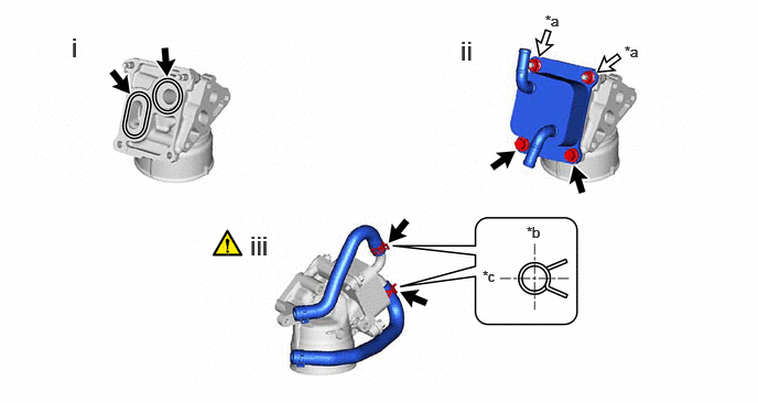
| *a | Nut | *b | Upward |
| *c | Rearward | - | - |
Install a new gasket and new O-ring.
Install the oil cooler assembly with the 2 bolts and 2 nuts.
- Torque:
- 21 N*m (214 kgf*cm, 15 ft.*lbf)
Connect the No. 8 water by-pass hose and No. 9 water by-pass hose to the oil cooler assembly and slide the 2 hose clamps to secure them.
- HINT:
-
The direction of the hose clamp is indicated in the illustration.
15671 3.INSTALL OIL FILTER BRACKET
16206 4.CONNECT WATER BY-PASS PIPE SUB-ASSEMBLY
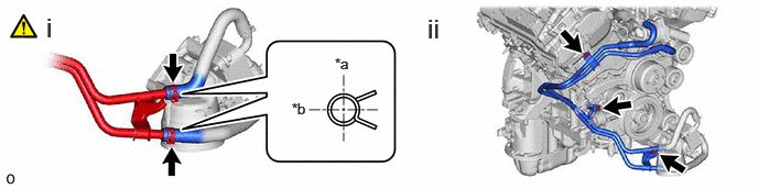
| *a | Upward | *b | Rearward |
Connect the No. 8 water by-pass hose and No. 9 water by-pass hose to the water by-pass pipe sub-assembly and slide the 2 hose clamps to secure them.
- HINT:
-
The direction of the hose clamp is indicated in the illustration.
Connect the water by-pass pipe sub-assembly with the 3 bolts.
- Torque:
- 10 N*m (102 kgf*cm, 7 ft.*lbf)
5.INSTALL OIL FILTER ELEMENT
6.ADD ENGINE OIL
7.ADD ENGINE COOLANT
8.INSPECT ENGINE OIL LEVEL
9.INSPECT FOR OIL LEAK
10.INSPECT FOR COOLANT LEAK
51420 11.INSTALL NO. 2 ENGINE UNDER COVER ASSEMBLY
51410 12.INSTALL NO. 1 ENGINE UNDER COVER ASSEMBLY