AJA0F AUTOMATIC TRANSMISSION / TRANSAXLE AUTOMATIC TRANSMISSION ASSEMBLY(for F33A-FTV) INSTALLATION
CAUTION / NOTICE / HINT
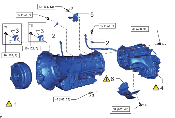
| Procedure | Part Name Code |

|

|

|
|
|---|---|---|---|---|---|
| 1 | TORQUE CONVERTER ASSEMBLY | 32000 | ( ) |
- | - |
| 2 | INSTALL WIRE HARNESS CLAMP BRACKET | - | - | - | - |
| 3 | EXHAUST SENSOR CLAMP BRACKET | - | - | - | - |
| 4 | TRANSFER ASSEMBLY | 36100 | () |
- | - |
| 5 | EXHAUST PIPE SUPPORT BRACKET ASSEMBLY | 17570 | - | - | - |
| 6 | REAR ENGINE MOUNTING INSULATOR | 12371A | () |
- | - |
| *A | for Type A | *B | for Type B |

|
Tightening torque for "Major areas involving basic vehicle performance such as moving/turning/stopping": N*m (kgf*cm, ft.*lbf) |

|
N*m (kgf*cm, ft.*lbf): Specified torque |
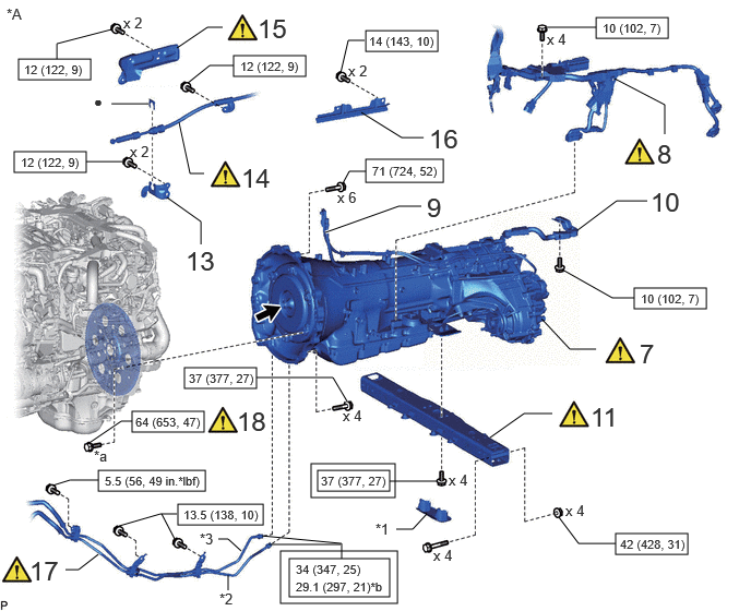
| Procedure | Part Name Code |
|
|
|
|
|---|---|---|---|---|---|
| 7 | AUTOMATIC TRANSMISSION ASSEMBLY WITH TRANSFER ASSEMBLY | - | () |
- | - |
| 8 | WIRE HARNESS | - | () |
- | - |
| 9 | TRANSFER BREATHER HOSE SUB-ASSEMBLY | 36407 | - | - | - |
| 10 | CONNECT WIRE HARNESS CLAMP BRACKET | - | - | - | - |
| 11 | NO. 3 FRAME CROSSMEMBER ASSEMBLY | - | () |
- | - |
| 13 | NO. 1 TRANSMISSION CONTROL CABLE BRACKET | 33823 | - | - | - |
| 14 | TRANSMISSION CONTROL CABLE ASSEMBLY | 33820B | () |
- | - |
| 15 | TRANSMISSION CONTROL CABLE INSULATOR | 33825 | () |
- | - |
| 16 | TRANSMISSION INSULATOR RH | 35979B | - | - | - |
| 17 | OIL COOLER TUBE SUB-ASSEMBLY | - | () |
- | - |
| 18 | DRIVE PLATE AND TORQUE CONVERTER SETTING BOLT | 32101A | () |
- | - |
| *A | w/o Urea SCR System | - | - |
| *1 | NO. 3 ENGINE MOUNTING HOLE COVER | *2 | NO. 1 OIL COOLER INLET TUBE |
| *3 | OIL COOLER OUTLET TUBE | - | - |
| *a | Black: x 1 Silver: x 5 |
*b | For use with union nut wrench |
|
|
Tightening torque for "Major areas involving basic vehicle performance such as moving/turning/stopping": N*m (kgf*cm, ft.*lbf) |
|
N*m (kgf*cm, ft.*lbf): Specified torque |
| ● | Non-reusable part |

|
Clutch spline grease |
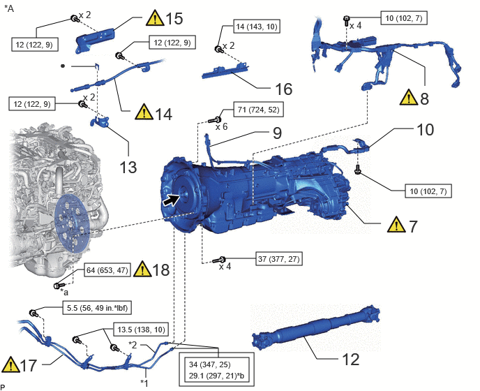
| Procedure | Part Name Code |
|
|
|
|
|---|---|---|---|---|---|
| 7 | AUTOMATIC TRANSMISSION ASSEMBLY WITH TRANSFER ASSEMBLY | - | () |
- | - |
| 8 | WIRE HARNESS | - | () |
- | - |
| 9 | TRANSFER BREATHER HOSE SUB-ASSEMBLY | 36407 | - | - | - |
| 10 | CONNECT WIRE HARNESS CLAMP BRACKET | - | - | - | - |
| 12 | FRONT PROPELLER SHAFT ASSEMBLY | 37140 | - | - | - |
| 13 | NO. 1 TRANSMISSION CONTROL CABLE BRACKET | 33823 | - | - | - |
| 14 | TRANSMISSION CONTROL CABLE ASSEMBLY | 33820B | () |
- | - |
| 15 | TRANSMISSION CONTROL CABLE INSULATOR | 33825 | () |
- | - |
| 16 | TRANSMISSION INSULATOR RH | 35979B | - | - | - |
| 17 | OIL COOLER TUBE SUB-ASSEMBLY | - | () |
- | - |
| 18 | DRIVE PLATE AND TORQUE CONVERTER SETTING BOLT | 32101A | () |
- | - |
| *A | w/ Urea SCR System | - | - |
| *1 | NO. 1 OIL COOLER INLET TUBE | *2 | OIL COOLER OUTLET TUBE |
| *a | Black: x 1 Silver: x 5 |
*b | For use with union nut wrench |
|
|
Tightening torque for "Major areas involving basic vehicle performance such as moving/turning/stopping": N*m (kgf*cm, ft.*lbf) |
|
N*m (kgf*cm, ft.*lbf): Specified torque |
| ● | Non-reusable part |
|
Clutch spline grease |
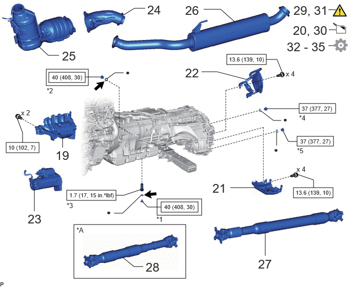
| Procedure | Part Name Code |
|
|
|
|
|---|---|---|---|---|---|
| 19 | OIL PAN COVER SILENCER | 12144 | - | - | - |
| 20 | ADD TRANSFER OIL | - | - | () |
- |
| 21 | LOWER TRANSFER CASE PROTECTOR | 36179 | - | - | - |
| 22 | TRANSFER HEAT INSULATOR | 36336 | - | - | - |
| 23 | STARTER ASSEMBLY | 28100 | - | - | - |
| 24 | NO. 2 FRONT EXHAUST PIPE SUB-ASSEMBLY | 17402 | - | - | - |
| 25 | FRONT EXHAUST PIPE SUB-ASSEMBLY | 17401 | - | - | - |
| 26 | CENTER EXHAUST PIPE ASSEMBLY | 17420 | - | - | - |
| 27 | REAR PROPELLER SHAFT ASSEMBLY | 37110F | - | - | - |
| 28 | FRONT PROPELLER SHAFT ASSEMBLY | 37140 | - | - | - |
| 29 | INSPECT SHIFT LEVER POSITION | - | () |
- | - |
| 30 | ADD AND ADJUST AUTOMATIC TRANSMISSION FLUID | - | - | () |
- |
| 31 | INSPECT FOR EXHAUST GAS LEAK | - | - | - | - |
| 32 | ECU CONFIGURATION | - | - | - | () |
| 33 | UPDATE ECU SECURITY KEY | - | - | - | () |
| 34 | RESET MEMORY | - | - | - | () |
| 35 | ATF THERMAL DEGRADATION ESTIMATE RESET | - | - | - | () |
| *A | w/o Urea SCR System | - | - |
| *1 | OVERFLOW PLUG | *2 | REFILL PLUG |
| *3 | NO. 1 TRANSMISSION OIL FILLER TUBE | *4 | FILLER PLUG |
| *5 | DRAIN PLUG | - | - |
|
|
Tightening torque for "Major areas involving basic vehicle performance such as moving/turning/stopping": N*m (kgf*cm, ft.*lbf) |
|
N*m (kgf*cm, ft.*lbf): Specified torque |
| ● | Non-reusable part |
|
Toyota Genuine ATF WS |
PROCEDURE

 32000 1.INSTALL TORQUE CONVERTER ASSEMBLY
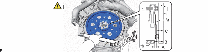
| *1 | Straightedge | - | - |
| *a | Torque converter assembly contact surface of the drive plate | *b | Automatic transmission assembly with transfer assembly contact surface of the engine assembly |
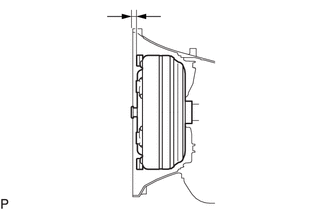
Using a vernier caliper and straightedge, measure the dimension A between the automatic transmission assembly with transfer assembly contact surface of the engine assembly and the torque converter assembly contact surface of the drive plate.
- Measurement Method:
-
B - C = A
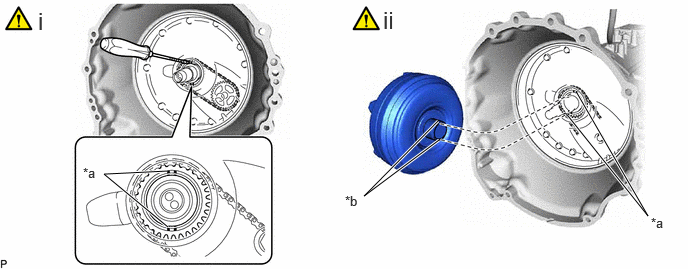
| *a | Protrusion of the Oil Pump Drive Sprocket | *b | Cutout |
Using a screwdriver with its tip wrapped with protective tape, align the oil pump drive sprocket so that it is perpendicular as shown in the illustration.
- NOTICE:
-
Do not damage the front oil pump cover seal.
Align the cutout on the torque converter assembly with the protrusion on the oil pump drive sprocket and attach the spline on the input shaft to the spline on the turbine liner.
- NOTICE:
-
·
Install the torque converter assembly to the input shaft while keeping it horizontal.
·Do not damage the front oil pump cover seal.
·Make sure the cutout on the torque converter assembly and the protrusion on the oil pump drive sprocket are properly aligned.
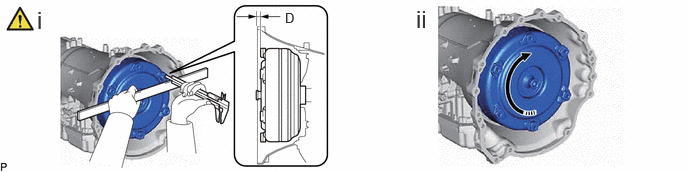

|
Rotates Smoothly | - | - |
Using a vernier caliper and straightedge, measure the dimension D shown in the illustration and check that the dimension D is more than the dimension A, which was measured in the previous step.
- Standard:
-
Dimension D = Dimension A + 1.0 mm (0.0394 in.) or more
Check that the torque converter assembly rotates smoothly.
2.INSTALL WIRE HARNESS CLAMP BRACKET
- Torque:
- 10 N*m (102 kgf*cm, 7 ft.*lbf)
3.INSTALL EXHAUST SENSOR CLAMP BRACKET
- Torque:
- 10 N*m (102 kgf*cm, 7 ft.*lbf)
36100 4.INSTALL TRANSFER ASSEMBLY
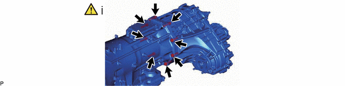
Install the transfer assembly to the automatic transmission assembly with the 8 bolts.
- Torque:
- 40 N*m (408 kgf*cm, 30 ft.*lbf)
- NOTICE:
-
When installing the transfer assembly to the automatic transmission assembly, make sure that the automatic transmission assembly and oil seal do not become damaged.
17570 5.INSTALL EXHAUST PIPE SUPPORT BRACKET ASSEMBLY
- Torque:
- 43 N*m (438 kgf*cm, 32 ft.*lbf)
12371A 6.INSTALL REAR ENGINE MOUNTING INSULATOR
|
|
Click here() |
7.INSTALL AUTOMATIC TRANSMISSION ASSEMBLY WITH TRANSFER ASSEMBLY
|
|
|
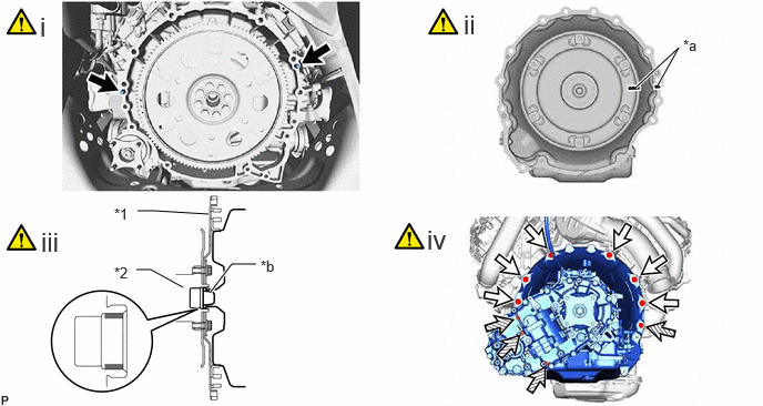
| *1 | Drive Plate | *2 | Crankshaft |
| *a | Matchmark | *b | Torque Converter Assembly Centerpiece |
|
|
Knock Pin |

|
Bolt A |

|
Bolt B |

|
Clutch Spline Grease |
Confirm that the 2 knock pins are installed to the engine assembly and are not damaged.
Make sure that the matchmark is positioned as shown in the illustration.
Apply clutch spline grease to the surface the crankshaft that contacts the torque converter assembly centerpiece.
- Clutch Spline Grease:
-
Toyota Genuine Clutch Spline Grease or equivalent
- Maximum Grease Amount:
-
Approximately 1 g (0.0353 oz.)
While keeping the engine assembly and automatic transmission assembly with transfer assembly horizontal, align the 2 knock pins with the holes in the automatic transmission assembly with transfer assembly and install the automatic transmission assembly with transfer assembly with the 10 bolts.
- Torque:
- for bolt A : 71 N*m (724 kgf*cm, 52 ft.*lbf)
- for bolt B : 37 N*m (377 kgf*cm, 27 ft.*lbf)
- NOTICE:
-
·
Do not use excessive force when installing the automatic transmission assembly with transfer assembly.
·When mounting the automatic transmission assembly with transfer assembly to the engine assembly, make sure to securely fit the 2 knock pins into the knock holes.
·When tightening the bolts, make sure that the contact surfaces of the engine assembly and the automatic transmission assembly with transfer assembly are in close contact with one another.
·When installing the automatic transmission assembly with transfer assembly, make sure that the oil cooler tube does not become damaged.
·Check that the torque converter assembly rotates smoothly after installation of the automatic transmission assembly with transfer assembly.
- HINT:
-
Item Length Bolt A 50 mm (1.97 in.) Bolt B 45 mm (1.77 in.)
8.CONNECT WIRE HARNESS
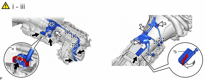
| *a | Transmission Wire Connector | *b | TCM connector |
|
|
Connector |
|
Bolt |
|
|
Push Up |

|
Securely Lock |
Connect the wire harness to the automatic transmission assembly with transfer assembly with the 4 bolts.
- Torque:
- 10 N*m (102 kgf*cm, 7 ft.*lbf)
Attach the clamp.
Connect the 5 connectors.
- NOTICE:
-
·
Push up the lever until the claw of the transmission wire connector makes a connection sound.
·Securely lock the TCM connector lever.
36407 9.CONNECT TRANSFER BREATHER HOSE SUB-ASSEMBLY
10.CONNECT WIRE HARNESS CLAMP BRACKET
11.INSTALL NO. 3 FRAME CROSSMEMBER ASSEMBLY (w/o Urea SCR System)
|
|
() |
37140 12.INSTALL FRONT PROPELLER SHAFT ASSEMBLY (w/ Urea SCR System)
Click hereDrivetrain>DRIVE SHAFT / PROPELLER SHAFT>FRONT PROPELLER SHAFT ASSEMBLY>INSTALLATION
- HINT:
-
Install the under cover after completing the adjustment and inspection procedure.
33823 13.INSTALL NO. 1 TRANSMISSION CONTROL CABLE BRACKET
- Torque:
- 12 N*m (122 kgf*cm, 9 ft.*lbf)
33820B 14.CONNECT TRANSMISSION CONTROL CABLE ASSEMBLY
|
|
() |
33825 15.INSTALL TRANSMISSION CONTROL CABLE INSULATOR
|
|
() |
35979B 16.INSTALL TRANSMISSION INSULATOR RH
- Torque:
- 14 N*m (143 kgf*cm, 10 ft.*lbf)
17.CONNECT OIL COOLER TUBE SUB-ASSEMBLY
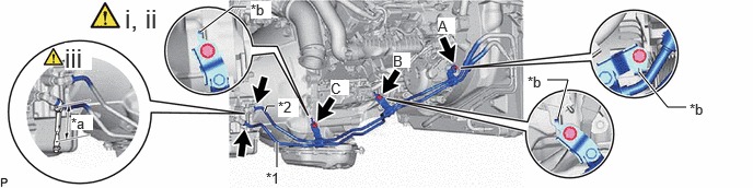
| *1 | No. 1 Oil Cooler Inlet Tube | *2 | Oil Cooler Outlet Tube |
| *a | Torque Wrench Fulcrum Length | *b | Stopper |
Temporarily connect the No. 1 oil cooler inlet tube and oil cooler outlet tube to the automatic transmission assembly with transfer assembly.
Connect the oil cooler tube sub-assembly to the automatic transmission assembly with transfer assembly and engine assembly with the 3 bolts.
- Torque:
- for bolt A : 5.5 N*m (56 kgf*cm, 49 in.*lbf)
- for bolt B and bolt C : 13.5 N*m (138 kgf*cm, 10 ft.*lbf)
- NOTICE:
-
Check that the stopper is secure.
- HINT:
-
Tightening order: Temporarily install bolt (A) → Tighten bolt (B) → Tighten bolt (C) → Tighten bolt (A)
-
Item Thread Diameter Bolt A 6 mm (0.236 in.) Bolt B 8 mm (0.315 in.) Bolt C 8 mm (0.315 in.)
Using a 17 mm union nut wrench, tighten the No. 1 oil cooler inlet tube and oil cooler outlet tube.
- Torque:
- 34 N*m (347 kgf*cm, 25 ft.*lbf)
- HINT:
-
·
Calculate the torque wrench reading when changing the fulcrum length of the torque wrench.
Click hereGeneral>INTRODUCTION>REPAIR INSTRUCTION>PRECAUTION
·When using a union nut wrench (fulcrum length of 30 mm (1.1811 in.)) + torque wrench (fulcrum length of 180 mm (7.0866 in.)): 29.1 N*m (297 kgf*cm, 21 ft.*lbf)
32101A 18.INSTALL DRIVE PLATE AND TORQUE CONVERTER SETTING BOLT
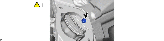
Install the torque converter assembly to the drive plate and ring gear sub-assembly with the 6 drive plate and torque converter setting bolts.
- Torque:
- 64 N*m (653 kgf*cm, 47 ft.*lbf)
- NOTICE:
-
Start by tightening the positioning drive plate and torque converter setting bolt (black), and then uniformly tighten the remaining 5 drive plate and torque converter setting bolts (silver).
- HINT:
-
Turn the crankshaft to a position where the drive plate and torque converter setting bolts can be installed, and install the drive plate and torque converter setting bolts while securing the crankshaft pulley bolt with a wrench.
12144 19.CONNECT OIL PAN COVER SILENCER
- Torque:
- 10 N*m (102 kgf*cm, 7 ft.*lbf)
20.ADD TRANSFER OIL
|
|
Click here() |
36179 21.INSTALL LOWER TRANSFER CASE PROTECTOR
36336 22.INSTALL TRANSFER HEAT INSULATOR
28100 23.INSTALL STARTER ASSEMBLY
for 2.0 kW Type
Click hereEngine / Hybrid System>F33A-FTV (STARTING)>STARTER (for 2.0 kW Type)>INSTALLATION
for 2.7 kW Type
Click hereEngine / Hybrid System>F33A-FTV (STARTING)>STARTER (for 2.7 kW Type)>INSTALLATION
w/ Stop and Start System
Click hereEngine / Hybrid System>F33A-FTV (STARTING)>STARTER (w/ Stop And Start System)>INSTALLATION
- HINT:
-
Install the under cover after completing the adjustment and inspection procedure.
17402 24.INSTALL NO. 2 FRONT EXHAUST PIPE SUB-ASSEMBLY
Click hereEngine / Hybrid System>F33A-FTV (EMISSION CONTROL)>MONOLITHIC CONVERTER (for Rear Side)>INSTALLATION
- HINT:
-
Install the under cover after completing the adjustment and inspection procedure.
17401 25.INSTALL FRONT EXHAUST PIPE SUB-ASSEMBLY
Click hereEngine / Hybrid System>F33A-FTV (EMISSION CONTROL)>MONOLITHIC CONVERTER (for Rear Side)>INSTALLATION
- HINT:
-
Install the under cover after completing the adjustment and inspection procedure.
17420 26.INSTALL CENTER EXHAUST PIPE ASSEMBLY
Click hereEngine / Hybrid System>F33A-FTV (INTAKE / EXHAUST)>EXHAUST PIPE>INSTALLATION
- HINT:
-
Install the under cover after completing the adjustment and inspection procedure.
37110F 27.INSTALL REAR PROPELLER SHAFT ASSEMBLY
Click hereDrivetrain>DRIVE SHAFT / PROPELLER SHAFT>PROPELLER SHAFT ASSEMBLY>INSTALLATION
- HINT:
-
Install the under cover after completing the adjustment and inspection procedure.
37140 28.INSTALL FRONT PROPELLER SHAFT ASSEMBLY (w/o Urea SCR System)
Click hereDrivetrain>DRIVE SHAFT / PROPELLER SHAFT>FRONT PROPELLER SHAFT ASSEMBLY>INSTALLATION
- HINT:
-
Install the under cover after completing the adjustment and inspection procedure.
29.INSPECT SHIFT LEVER POSITION
|
|
() |
30.ADD AND ADJUST AUTOMATIC TRANSMISSION FLUID
31.INSPECT FOR EXHAUST GAS LEAK
32. ECU CONFIGURATION
|
|
|
33. UPDATE ECU SECURITY KEY
34.RESET MEMORY
|
|
Click here() |
35. ATF THERMAL DEGRADATION ESTIMATE RESET
|
|
|