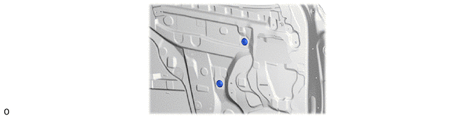
DOOR / HATCH FRONT DOOR DISASSEMBLY
CAUTION / NOTICE / HINT
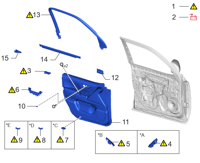
| Procedure | Part Name Code |

|

|

|
|
|---|---|---|---|---|---|
| 1 | PRECAUTION | - | ( ) |
- | - |
| 2 | DISCONNECT CABLE FROM NEGATIVE AUXILIARY BATTERY TERMINAL | - | - | - | - |
| 3 | FRONT DOOR TRIM UPPER COVER | 67782 | () |
- | - |
| 4 | MULTIPLEX NETWORK MASTER SWITCH ASSEMBLY WITH FRONT DOOR ARMREST BASE PANEL | - | () |
- | - |
| 5 | POWER WINDOW REGULATOR SWITCH ASSEMBLY WITH FRONT DOOR ARMREST BASE PANEL | - | () |
- | - |
| 6 | FRONT DOOR ARMREST COVER | 74222A | () |
- | - |
| 7 | COURTESY LIGHT ASSEMBLY | 81230 | () |
- | - |
| 8 | REFLEX REFLECTOR ASSEMBLY | 81580C | () |
- | - |
| 9 | FRONT DOOR HOLE COVER | 67811C | () |
- | - |
| 10 | NO. 1 FRONT DOOR STIFFENER CUSHION | 67923E | - | - | - |
| 11 | FRONT DOOR TRIM BOARD SUB-ASSEMBLY | 67602 | - | - | - |
| 12 | FRONT DOOR INSIDE HANDLE SUB-ASSEMBLY | 69206B | - | - | - |
| 13 | DOOR FRAME GARNISH | 67664C | () |
- | - |
| 14 | FRONT DOOR GLASS INNER WEATHERSTRIP | 68172A | - | - | - |
| 15 | FRONT DOOR PANEL PROTECTOR | 67856B | - | - | - |
| *A | for Driver Side | *B | for Front Passenger Side |
| *C | w/ Courtesy Light | *D | w/ Reflex Reflector Assembly |
| *E | w/ Cover | - | - |
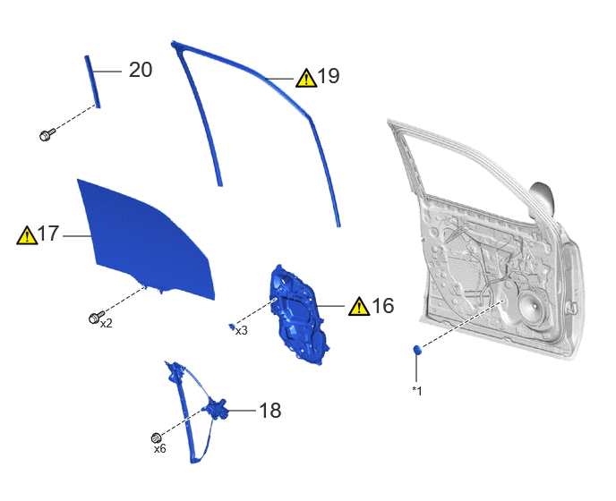
| Procedure | Part Name Code |
|
|
|
|
|---|---|---|---|---|---|
| 16 | FRONT DOOR SERVICE HOLE COVER | 67832 | () |
- | - |
| 17 | FRONT DOOR GLASS SUB-ASSEMBLY | 68102 | () |
- | - |
| 18 | FRONT DOOR WINDOW REGULATOR SUB-ASSEMBLY | 69802 | - | - | - |
| 19 | FRONT DOOR GLASS RUN | 68151E | - | - | - |
| 20 | FRONT DOOR REAR LOWER FRAME SUB-ASSEMBLY | 67404F | - | - | - |
| *1 | HOLE PLUG | - | - |
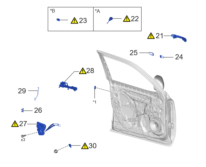
| Procedure | Part Name Code |
|
|
|
|
|---|---|---|---|---|---|
| 21 | FRONT DOOR OUTSIDE HANDLE ASSEMBLY | 69220 | () |
- | - |
| 22 | FRONT DOOR LOCK CYLINDER ASSEMBLY | - | () |
- | - |
| 23 | FRONT DOOR OUTSIDE HANDLE COVER | 69217D | () |
- | - |
| 24 | FRONT DOOR OUTSIDE HANDLE FRONT PAD | 69241H | - | - | - |
| 25 | FRONT DOOR OUTSIDE HANDLE REAR PAD | 69242E | - | - | - |
| 26 | DOOR LOCK COVER SET | 69032 | - | - | - |
| 27 | FRONT DOOR LOCK WITH MOTOR ASSEMBLY | 69040A | () |
- | - |
| 28 | FRONT DOOR OUTSIDE HANDLE FRAME SUB-ASSEMBLY | 69202A | () |
- | - |
| 29 | FRONT DOOR LOCK OPEN ROD | 69312 | - | - | - |
| 30 | SIDE AIRBAG PRESSURE SENSOR | 8983AA | () |
- | - |
| *A | for Driver Side | *B | for Front Passenger Side |
| *1 | HOLE PLUG | - | - |
| Procedure | Part Name Code |
|
|
|
|
|---|---|---|---|---|---|
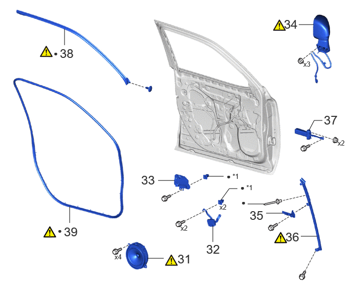
| 31 | FRONT NO. 1 SPEAKER ASSEMBLY | 86160 | () |
- | - |
| 32 | OUTER MIRROR CONTROL ECU ASSEMBLY | 89430A | () |
- | - |
| 33 | OUTER MIRROR INSTALL HOLE COVER | 87964 | - | - | - |
| 34 | OUTER REAR VIEW MIRROR ASSEMBLY | 87940 | () |
- | - |
| 35 | FRONT DOOR VENT SEAL | 67838D | - | - | - |
| 36 | FRONT DOOR FRONT LOWER FRAME SUB-ASSEMBLY | 67402F | - | - | - |
| 37 | FRONT DOOR NO. 2 WEATHERSTRIP | 67864H | - | - | - |
| 38 | FRONT DOOR CHECK ASSEMBLY | 68620 | () |
- | - |
| 39 | FRONT DOOR WEATHERSTRIP | 67862 | () |
- | - |
| *1 | GROMMET | - | - |
| ● | Non-reusable part | - | - |
| Procedure | Part Name Code |
|
|
|
|
|---|---|---|---|---|---|
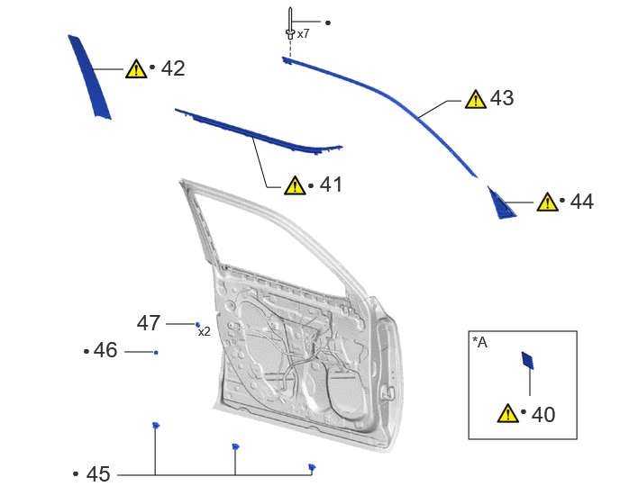
| 40 | FRONT FENDER NO. 1 NAME PLATE | 75361A | - | - | - |
| 41 | FRONT DOOR BELT MOULDING ASSEMBLY | 75720 | () |
- | - |
| 42 | FRONT DOOR REAR WINDOW FRAME MOULDING | 75756C | () |
- | - |
| 43 | FRONT DOOR UPPER WINDOW FRAME MOULDING | 75754A | () |
- | - |
| 44 | FRONT DOOR FRONT LOWER FRAME UPPER COVER | 67496C | () |
- | - |
| 45 | FRONT DOOR DUST PROOF SEAL | 67837B | - | - | - |
| 46 | FRONT DOOR PANEL CUSHION | 67001A | - | - | - |
| 47 | HOLE COVER | - | - | - | - |
| *A | for GR SPORT | - | - |
| ● | Non-reusable part | - | - |
CAUTION / NOTICE / HINT
The necessary procedures (adjustment, calibration, initialization, or registration) that must be performed after parts are removed and installed, or replaced during the front door removal/installation are shown below.
| Replaced Part or Performed Procedure | Necessary Procedure | Effect/Inoperative Function when Necessary Procedure not Performed | Link |
|---|---|---|---|
| Disconnect cable from negative auxiliary battery terminal | Memorize steering angle neutral point | Parking assist monitor system | () |
| Multi-terrain Monitor system | () |
||
| Panoramic view monitor system | () |
||
|
·
Door window regulator assembly
·
Door glass sub-assembly
·
Door glass run |
Initialize power window control system |
·
Auto up and down function
·
Jam protection function
·
Catch protection function
·
Remote control function
·
key-linked function
·
Wireless transmitter-linked function
·
Key-off operation function
·
Window open warning function |
() |
- HINT:
-
When the cable is disconnected/reconnected to the auxiliary battery terminal, systems temporarily stop operating. However, each system has a function that completes learning the first time the system is used.
-
·
Learning completes when vehicle is driven
Effect/Inoperative Function When Necessary Procedure not Performed Necessary Procedures Link Stop and start system Drive the vehicle until stop and start control is permitted (approximately 5 to 60 minutes) ( )Lighting system (EXT) Cornering lights Drive the vehicle straight ahead at 35 km/h (22 mph) or more for 5 seconds or more. ( )Pre-collision system Lane tracing assist system Lane departure alert system Adaptive high beam system
·Learning completes when vehicle is operated normally
Effect/Inoperative Function when Necessary Procedure not Performed Necessary Procedures Link Power back door system Fully close the back door by hand.
- HINT:
-
Initialization is not necessary if the above procedures are performed while the back door is closed.
( )Air conditioning system After the ignition switch is turned to ON, the servo motor and expansion valve standard position is recognized. -
- HINT:
-
·
Use the same procedure for the LH side and RH side.
·The following procedure is for the LH side.
PROCEDURE

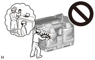
 1. PRECAUTION
|
|
|
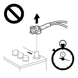
2.DISCONNECT CABLE FROM NEGATIVE AUXILIARY BATTERY TERMINAL
|
|
|
for 1GR-FE:
for V35A-FTS:
for F33A-FTV:
67782 3.REMOVE FRONT DOOR TRIM UPPER COVER
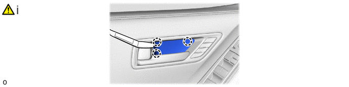
Using a moulding remover A, disengage the claws and remove the front door trim upper cover.
4.REMOVE MULTIPLEX NETWORK MASTER SWITCH ASSEMBLY WITH FRONT DOOR ARMREST BASE PANEL (for Driver Side)
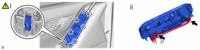
Using a moulding remover A, disengage the claws and clips to remove the multiplex network master switch assembly with front door armrest base panel.
Disconnect the connectors.
5.REMOVE POWER WINDOW REGULATOR SWITCH ASSEMBLY WITH FRONT DOOR ARMREST BASE PANEL (for Front Passenger Side)
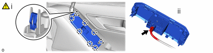
Using a moulding remover A, disengage the claws and clips to remove the power window regulator switch assembly with front door armrest base panel.
Disconnect the connector.
74222A 6.REMOVE FRONT DOOR ARMREST COVER
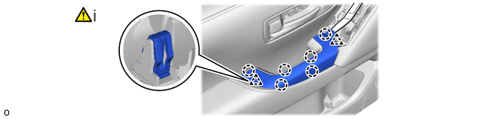
Using a moulding remover A, disengage the claws and clips to remove the front door armrest cover.
81230 7.REMOVE COURTESY LIGHT ASSEMBLY (w/ Courtesy Light)
|
|
Click here() |
81580C 8.REMOVE REFLEX REFLECTOR ASSEMBLY (w/ Reflex Reflector Assembly)
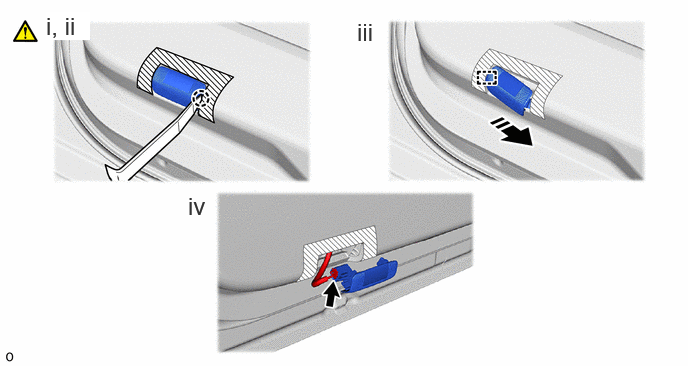

|
Remove in this Direction | - | - |
Apply protective tape as shown in the illustration.
Using a moulding remover A, disengage the claw.
Disengage the guide as shown in the illustration.
Disconnect the connector and remove the reflex reflector assembly.
67811C 9.REMOVE FRONT DOOR HOLE COVER (w/ Cover)
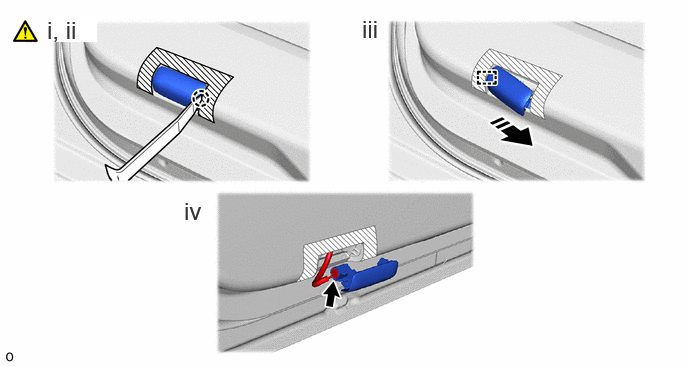
|
|
Remove in this Direction | - | - |
Apply protective tape as shown in the illustration.
Using a moulding remover A, disengage the claw.
Disengage the guide as shown in the illustration.
Disconnect the connector and remove the front door hole cover.
67923E 10.REMOVE NO. 1 FRONT DOOR STIFFENER CUSHION
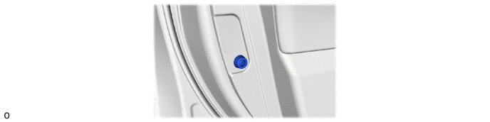
67602 11.REMOVE FRONT DOOR TRIM BOARD SUB-ASSEMBLY
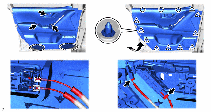

|
Place Hands Here |
|
Remove in this Direction |
69206B 12.REMOVE FRONT DOOR INSIDE HANDLE SUB-ASSEMBLY
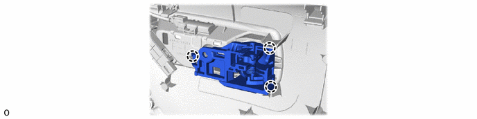
67664C 13.REMOVE DOOR FRAME GARNISH
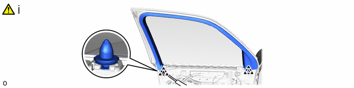
Using a clip remover with its tip wrapped in protective tape, disengage the 2 clips and remove the door frame garnish LH.
68172A 14.REMOVE FRONT DOOR GLASS INNER WEATHERSTRIP
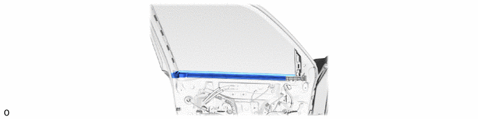
67856B 15.REMOVE FRONT DOOR PANEL PROTECTOR
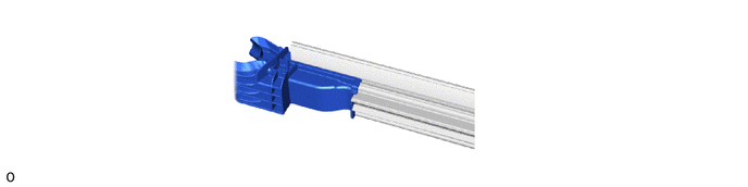
67832 16.REMOVE FRONT DOOR SERVICE HOLE COVER
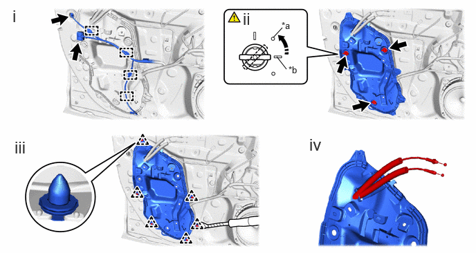
| *a | Location Mark | *b | Bead Mark |
|
|
Turn in this Direction | - | - |
Disconnect the 2 connectors and disengage the 4 clamps.
Turn the 3 front door service hole cover clips 45° to remove it clips as shown in the illustration.
Use the clip remover with its tip wrapped in protective tape, disengage the 6 clips to remove front door service hole cover.
Pull out the open lever front door lock remote control cable and front door inside lock and unlock knob locking cable from the front door service hole cover.
68102 17.REMOVE FRONT DOOR GLASS SUB-ASSEMBLY
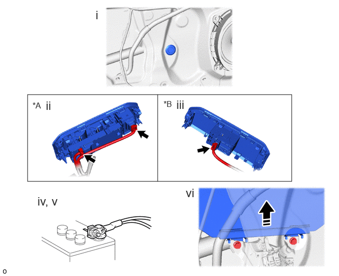
| *A | for Driver Side | *B | for Front Passenger Side |
|
|
Remove in this Direction | - | - |
Remove the hole plug.
for Driver Side:
1. Connect the 2 connectors to the multiplex network master switch assembly with front door armrest base panel.
for Front Passenger Side:
1. Connect the connector to the power window regulator switch assembly with front door armrest base panel.
Connect the cable to the negative (-) auxiliary battery terminal.
for 1GR-FE:
for V35A-FTS:
for F33A-FTV:
Turn the ignition switch to ON.
Move the front door glass sub-assembly so that the door glass bolts can be seen and turn the ignition switch to OFF.
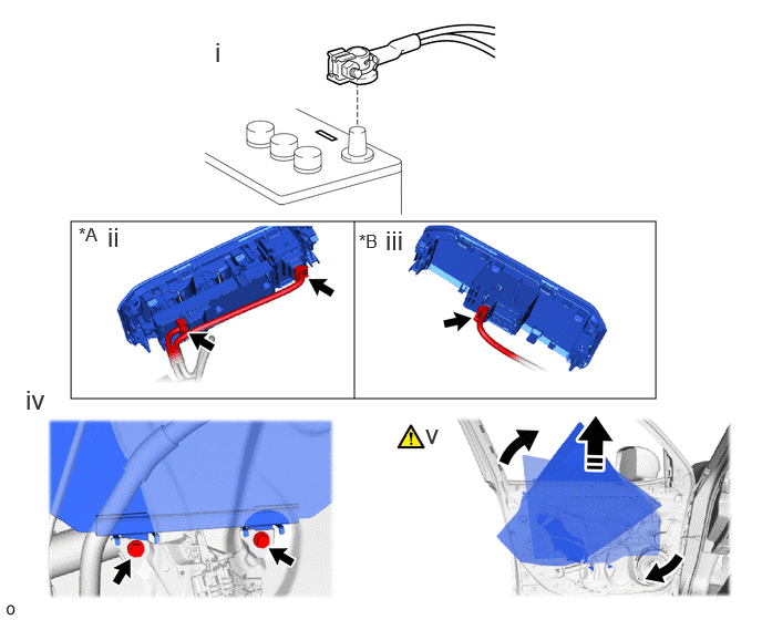
| *A | for Driver Side | *B | for Front Passenger Side |
|
|
Remove in this Direction | - | - |
Disconnect the cable from the negative (-) auxiliary battery terminal.
for 1GR-FE:
for V35A-FTS:
for F33A-FTV:
- CAUTION:
-
·
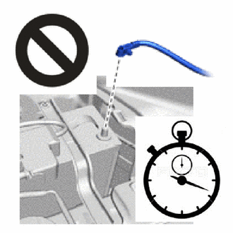
Wait at least 60 seconds after disconnecting the cable from the negative (-) auxiliary battery terminal to disable the SRS system.
·If an airbag deploys for any reason, it may cause a serious injury.
for Driver Side:
1. Disconnect the 2 connectors from the multiplex network master switch assembly with front door armrest base panel.
for Front Passenger Side:
1. Disconnect the connector from the power window regulator switch assembly with front door armrest base panel.
Remove the 2 bolts.
- NOTICE:
-
After the bolts are removed, do not allow the front door glass sub-assembly to fall.
Remove the front glass sub-assembly as shown in the illustration.
- NOTICE:
-
Do not damage the front door glass sub-assembly.
69802 18.REMOVE FRONT DOOR WINDOW REGULATOR SUB-ASSEMBLY
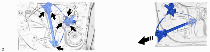
|
|
Remove in this Direction | - | - |
68151E 19.REMOVE FRONT DOOR GLASS RUN
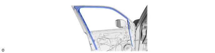
67404F 20.REMOVE FRONT DOOR REAR LOWER FRAME SUB-ASSEMBLY
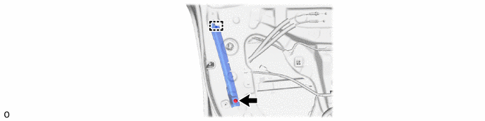
69220 21.REMOVE FRONT DOOR OUTSIDE HANDLE ASSEMBLY
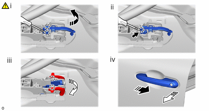
|
|
Remove in this Direction (1) |

|
Remove in this Direction (2) |
Using a screwdriver with its tip wrapped in protective tape, disengage the claws as shown in the illustration.
Using a screwdriver with its tip wrapped in protective tape, disconnect the connector.
Disengage the claws and move the lever as shown in the illustration.
Remove the front door outside handle assembly as shown in the illustration.
22.REMOVE FRONT DOOR LOCK CYLINDER ASSEMBLY (for Driver Side)
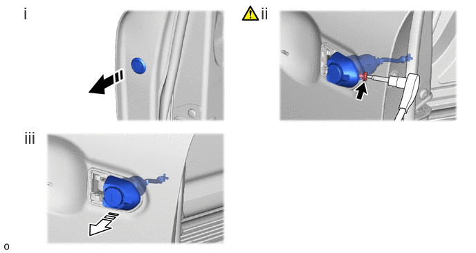
|
|
Remove in this Direction (1) |
|
Remove in this Direction (2) |
Remove the hole plug.
Using a T30 "TORX" socket wrench, loosen the "TORX" screw.
Remove the front door lock cylinder assembly as shown in the illustration.
69217D 23.REMOVE FRONT DOOR OUTSIDE HANDLE COVER (for Front Passenger Side)
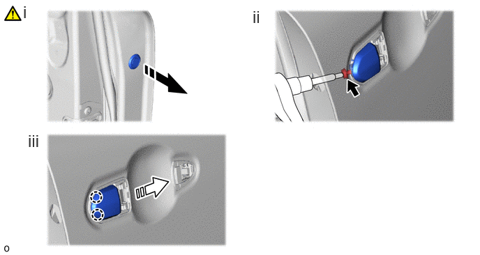
|
|
Remove in this Direction (1) |
|
Remove in this Direction (2) |
Remove the hole plug.
Using a T30 "TORX" socket wrench, loosen the "TORX" screw.
Remove the front door outside handle cover as shown in the illustration.
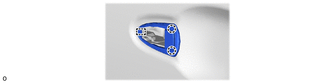
69241H 24.REMOVE FRONT DOOR OUTSIDE HANDLE FRONT PAD
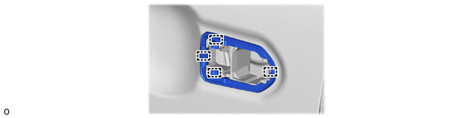
69242E 25.REMOVE FRONT DOOR OUTSIDE HANDLE REAR PAD
69032 26.REMOVE DOOR LOCK COVER SET
69040A 27.REMOVE FRONT DOOR LOCK WITH MOTOR ASSEMBLY
|
|
Click here() |
69202A 28.REMOVE FRONT DOOR OUTSIDE HANDLE FRAME SUB-ASSEMBLY
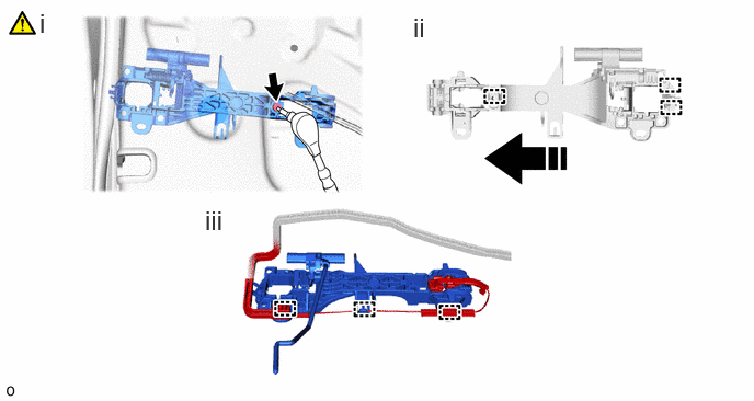
|
|
Remove in this Direction | - | - |
Using a T30 "TORX" socket wrench, remove the screw.
Disengage the guides to remove the front door outside handle frame sub-assembly as shown in the illustration.
Disengage the guide and clamps to separate the wire harness.
69312 29.REMOVE FRONT DOOR LOCK OPEN ROD
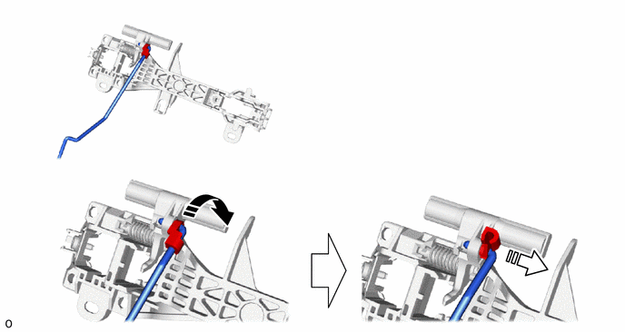
|
|
Remove in this Direction (1) |
|
Remove in this Direction (2) |
8983AA 30.REMOVE SIDE AIRBAG PRESSURE SENSOR
|
|
Click here() |
86160 31.REMOVE FRONT NO. 1 SPEAKER ASSEMBLY
|
|
Click here() |
89430A 32.REMOVE OUTER MIRROR CONTROL ECU ASSEMBLY
|
|
Click here() |
87964 33.REMOVE OUTER MIRROR INSTALL HOLE COVER
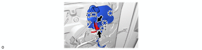
87940 34.REMOVE OUTER REAR VIEW MIRROR ASSEMBLY
|
|
Click here() |
67838D 35.REMOVE FRONT DOOR VENT SEAL
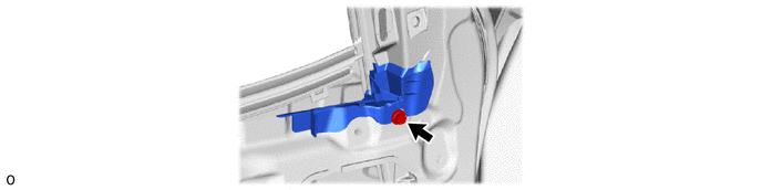
67402F 36.REMOVE FRONT DOOR FRONT LOWER FRAME SUB-ASSEMBLY
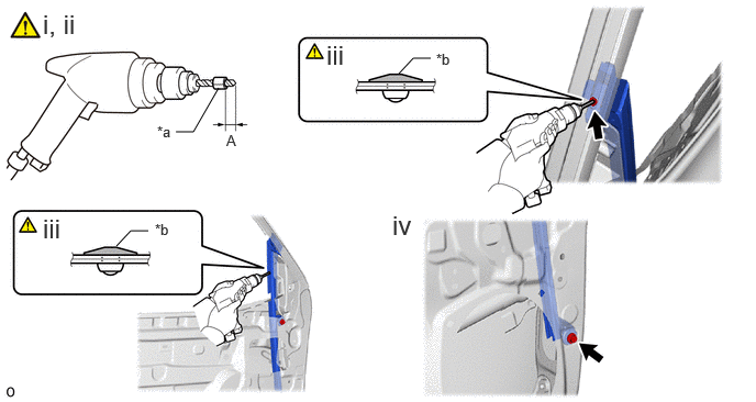
| *a | Tape | *b | Flange |
Insert a 4.0 mm (0.157 in.) drill bit into a drill.
Tape the 4.0 mm (0.157 in.) drill bit 5.0 mm (0.197 in.) from the tip as shown in the illustration.
- Standard Measurement:
-
Area Measurement Area Measurement A 5.0 mm (0.197 in.) - -
- NOTICE:
-
Tape the 4.0 mm (0.157 in.) drill bit to prevent the drill bit from going too deep.
Lightly press the drill against the rivets to drill off the rivet flange, and remove the rivets.
- CAUTION:
-
Be careful of the drilled rivet, as they may be hot.
- NOTICE:
-
·
Pressing the drill too firmly will cause the rivet to turn and result in the rivet not being drilled through.
·Prying the rivet with the drill may damage the rivet installation holes or drill bit.
Remove the bolt and front door front lower frame sub-assembly.
67864H 37.REMOVE FRONT DOOR NO. 2 WEATHERSTRIP
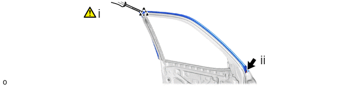
Using a clip remover with its tip wrapped in protective tape, disengage the clip.
Remove the clip and front door No. 2 weatherstrip
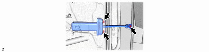
68620 38.REMOVE FRONT DOOR CHECK ASSEMBLY
67862 39.REMOVE FRONT DOOR WEATHERSTRIP
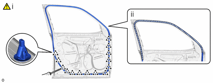

|
Double-sided Tape | - | - |
Using a clip remover with its tip wrapped in protective tape, disengage the clips.
Remove the double-sided tape and front door weatherstrip.
- NOTICE:
-
Remove any remaining double-sided tape from the front door panel.
75361A 40.REMOVE FRONT FENDER NO. 1 NAME PLATE (for GR SPORT)
|
|
Click here() |
75720 41.REMOVE FRONT DOOR BELT MOULDING ASSEMBLY
|
|
Click here() |
75756C 42.REMOVE FRONT DOOR REAR WINDOW FRAME MOULDING
|
|
Click here() |
75754A 43.REMOVE FRONT DOOR UPPER WINDOW FRAME MOULDING
|
|
Click here() |
67496C 44.REMOVE FRONT DOOR FRONT LOWER FRAME UPPER COVER
|
|
Click here() |
67837B 45.REMOVE FRONT DOOR DUST PROOF SEAL
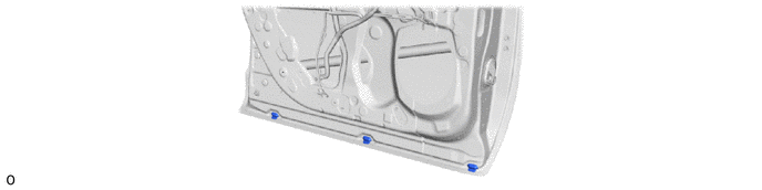
67001A 46.REMOVE FRONT DOOR PANEL CUSHION
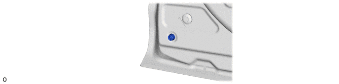
47.REMOVE HOLE COVER