LIGHTING (INT) LIGHTING SYSTEM Instrument Panel Illumination does not Turn On
DESCRIPTION
The power distribution box assembly controls the instrument panel illuminations.
WIRING DIAGRAM
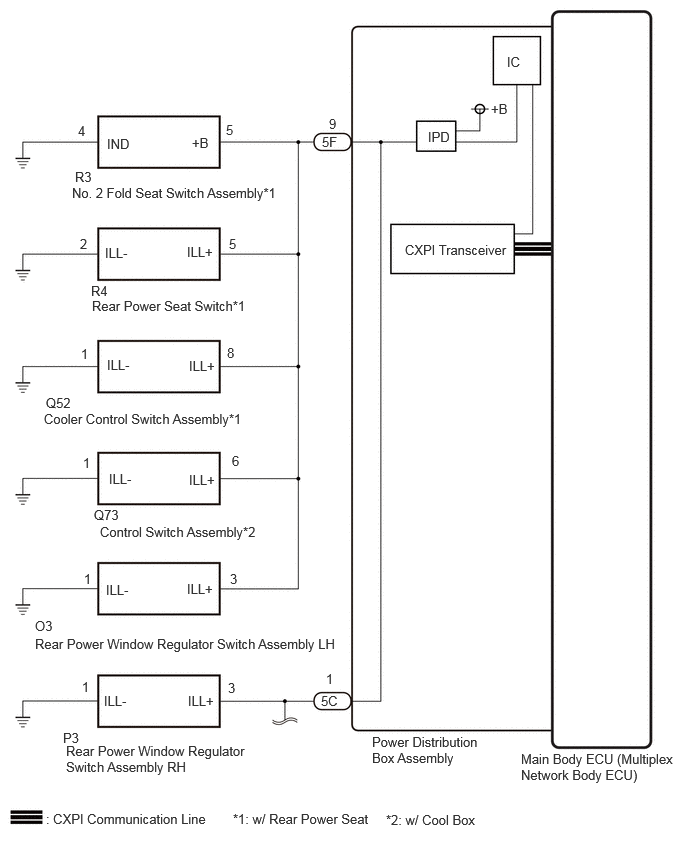
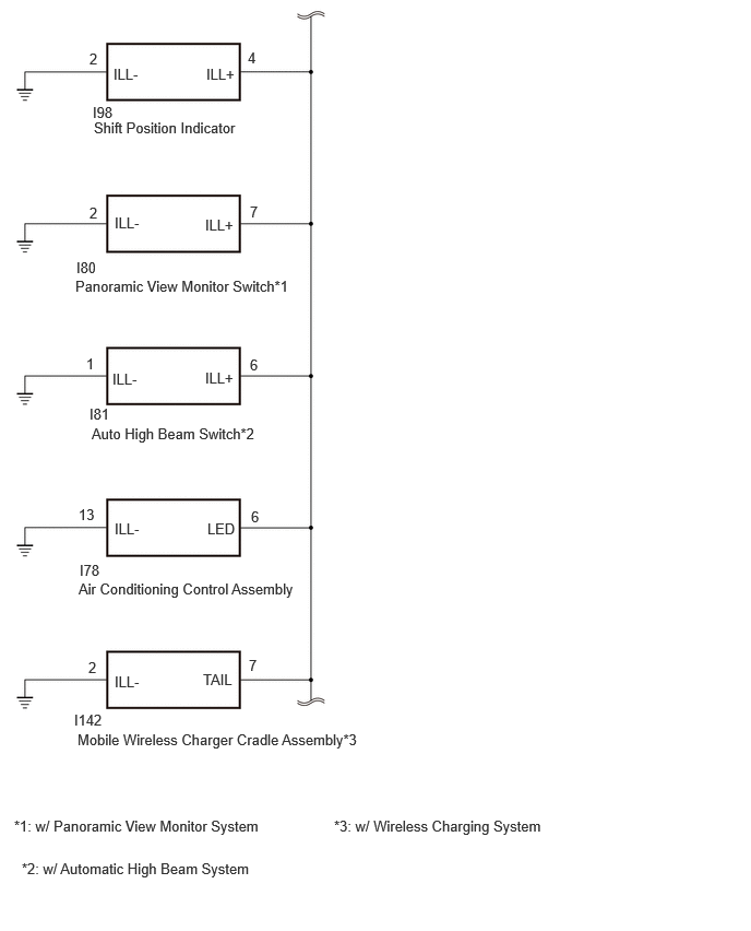
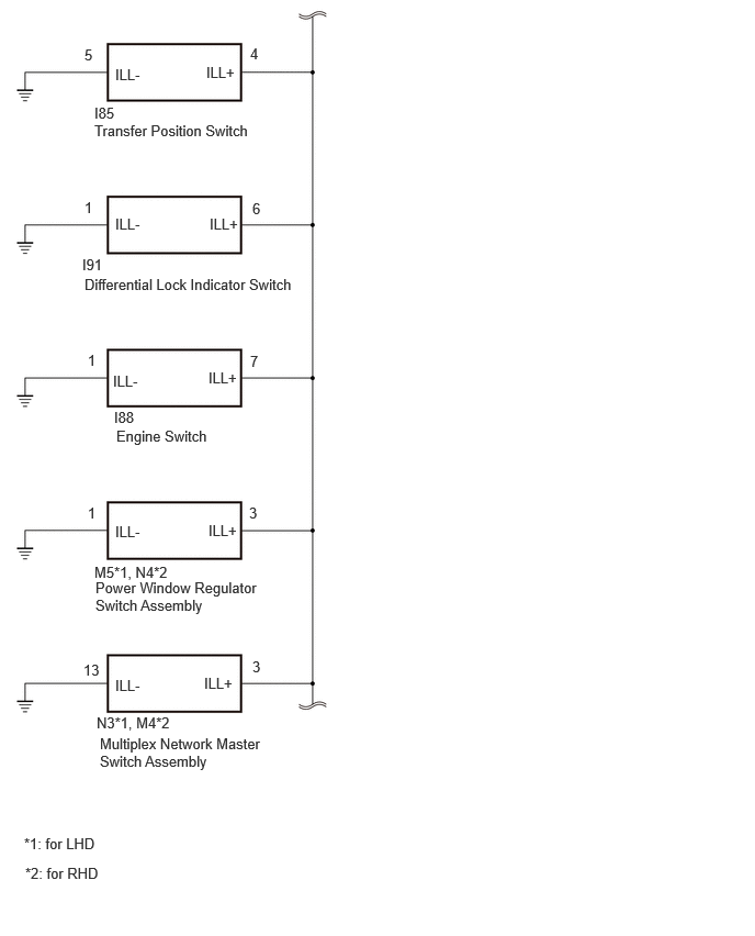
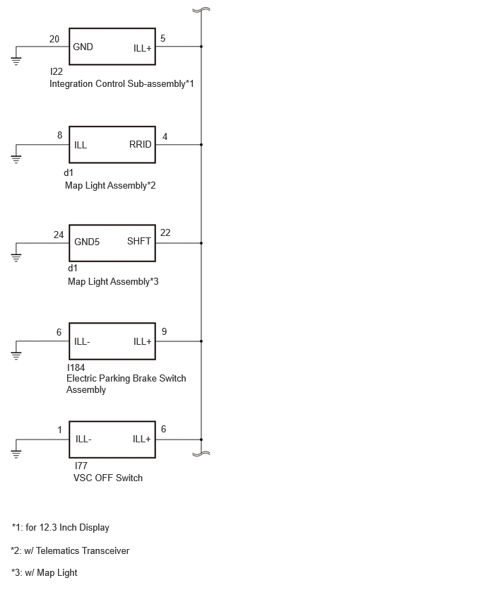
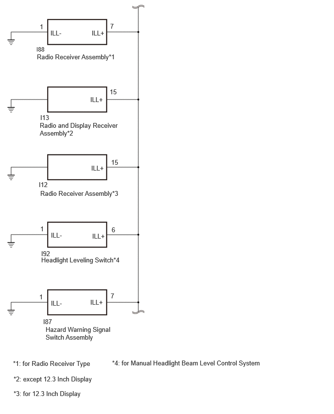
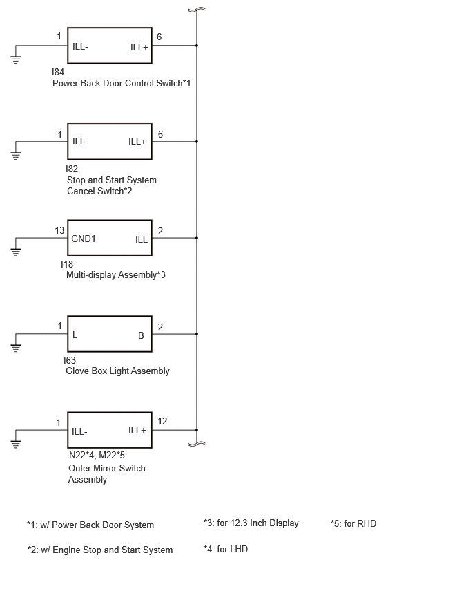
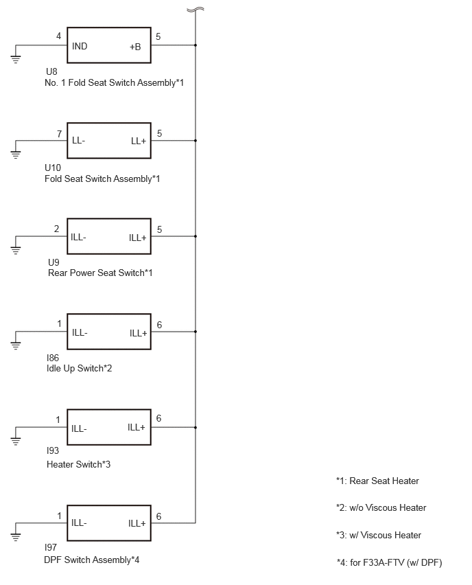
CAUTION / NOTICE / HINT
- NOTICE:
-
·
Inspect the fuses for circuits related to this system before performing the following inspection procedure.
·First perform the communication function inspections in How to Proceed with Troubleshooting to confirm that there are no CXPI communication malfunctions before troubleshooting this symptom.
Click hereVehicle Interior>LIGHTING (INT)>LIGHTING SYSTEM>HOW TO PROCEED WITH TROUBLESHOOTING
PROCEDURE
Read the Data List according to the display on the GTS.
- Body Electrical > Power Distribution Box > Data List
-
Tester Display Measurement Item Range Normal Condition Diagnostic Note Panel Light Input Signal Panel light input condition OFF or ON OFF: Light control switch not in HEAD position
ON: Light control switch in HEAD position-
- Body Electrical > Power Distribution Box > Data List
-
Tester Display Panel Light Input Signal - 50003 475 1295
- OK:
-
The GTS display changes correctly in response to the operation of the light control switch.
- Result:
-
Result Proceed to OK A NG (for LHD) B NG (for RHD) C
A
B
C
Read the Data List according to the display on the GTS.
- Body Electrical > Power Distribution Box > Data List
-
Tester Display Measurement Item Range Normal Condition Diagnostic Note Panel Light Output Signal Panel light output condition OFF or ON OFF: Taillight off
ON: Taillight on-
- Body Electrical > Power Distribution Box > Data List
-
Tester Display Panel Light Output Signal - 50003 475 1296
- OK:
-
The GTS display changes correctly in response to the operation of the light control switch.
- Result:
-
Result Proceed to OK A NG (for LHD) B NG (for RHD) C
A
B
C
Turn the light control switch to the HEAD position.
Read the Data List according to the display on the GTS.
- Body Electrical > Power Distribution Box > Data List
-
Tester Display Measurement Item Range Normal Condition Diagnostic Note Panel Light Fuse Shut Off Status Panel light fuse condition OFF or ON OFF: Fuse not shut off
ON: Fuse shut off-
- Body Electrical > Power Distribution Box > Data List
-
Tester Display Panel Light Fuse Shut Off Status - 50003 475 1298
- OK:
-
The Data List value displays "OFF".
- Result:
-
Proceed to OK NG
OK
NG
- NOTICE:
-
For vehicle without rear power seat, proceed to next step.
Disconnect the R3 No. 2 fold seat switch assembly connector.
Turn the light control switch to the HEAD position.
Read the Data List according to the display on the GTS.
- Body Electrical > Power Distribution Box > Data List
-
Tester Display Measurement Item Range Normal Condition Diagnostic Note Panel Light Fuse Shut Off Status Panel light fuse condition OFF or ON OFF: Fuse not shut off
ON: Fuse shut off-
- Body Electrical > Power Distribution Box > Data List
-
Tester Display Panel Light Fuse Shut Off Status - 50003 475 1298
- OK:
-
The Data List value displays "OFF".
- Result:
-
Proceed to OK NG
OK
NG
- NOTICE:
-
For vehicle without rear power seat, proceed to next step.
Disconnect the R4 rear power seat switch connector.
Turn the light control switch to the HEAD position.
Read the Data List according to the display on the GTS.
- Body Electrical > Power Distribution Box > Data List
-
Tester Display Measurement Item Range Normal Condition Diagnostic Note Panel Light Fuse Shut Off Status Panel light fuse condition OFF or ON OFF: Fuse not shut off
ON: Fuse shut off-
- Body Electrical > Power Distribution Box > Data List
-
Tester Display Panel Light Fuse Shut Off Status - 50003 475 1298
- OK:
-
The Data List value displays "OFF".
- Result:
-
Proceed to OK NG
OK
NG
- NOTICE:
-
For vehicle without rear seat heater, proceed to next step.
Disconnect the Q52 cooler control switch assembly connector.
Turn the light control switch to the HEAD position.
Read the Data List according to the display on the GTS.
- Body Electrical > Power Distribution Box > Data List
-
Tester Display Measurement Item Range Normal Condition Diagnostic Note Panel Light Fuse Shut Off Status Panel light fuse condition OFF or ON OFF: Fuse not shut off
ON: Fuse shut off-
- Body Electrical > Power Distribution Box > Data List
-
Tester Display Panel Light Fuse Shut Off Status - 50003 475 1298
- OK:
-
The Data List value displays "OFF".
- Result:
-
Proceed to OK NG
OK
Click hereVehicle Interior>HEATING / AIR CONDITIONING>AIR CONDITIONING PANEL (for Rear Side)>REMOVAL
NG
- NOTICE:
-
For vehicle without cooling box, proceed to next step.
Disconnect the Q73 control switch assembly connector.
Turn the light control switch to the HEAD position.
Read the Data List according to the display on the GTS.
- Body Electrical > Power Distribution Box > Data List
-
Tester Display Measurement Item Range Normal Condition Diagnostic Note Panel Light Fuse Shut Off Status Panel light fuse condition OFF or ON OFF: Fuse not shut off
ON: Fuse shut off-
- Body Electrical > Power Distribution Box > Data List
-
Tester Display Panel Light Fuse Shut Off Status - 50003 475 1298
- OK:
-
The Data List value displays "OFF".
- Result:
-
Proceed to OK NG
OK
NG
Disconnect the O3 rear power window regulator switch assembly LH connector.
Turn the light control switch to the HEAD position.
Read the Data List according to the display on the GTS.
- Body Electrical > Power Distribution Box > Data List
-
Tester Display Measurement Item Range Normal Condition Diagnostic Note Panel Light Fuse Shut Off Status Panel light fuse condition OFF or ON OFF: Fuse not shut off
ON: Fuse shut off-
- Body Electrical > Power Distribution Box > Data List
-
Tester Display Panel Light Fuse Shut Off Status - 50003 475 1298
- OK:
-
The Data List value displays "OFF".
- Result:
-
Proceed to OK NG
OK
NG
Disconnect the P3 rear power window regulator switch assembly RH connector.
Turn the light control switch to the HEAD position.
Read the Data List according to the display on the GTS.
- Body Electrical > Power Distribution Box > Data List
-
Tester Display Measurement Item Range Normal Condition Diagnostic Note Panel Light Fuse Shut Off Status Panel light fuse condition OFF or ON OFF: Fuse not shut off
ON: Fuse shut off-
- Body Electrical > Power Distribution Box > Data List
-
Tester Display Panel Light Fuse Shut Off Status - 50003 475 1298
- OK:
-
The Data List value displays "OFF".
- Result:
-
Proceed to OK NG
OK
NG
Disconnect the I98 shift position indicator connector.
Turn the light control switch to the HEAD position.
Read the Data List according to the display on the GTS.
- Body Electrical > Power Distribution Box > Data List
-
Tester Display Measurement Item Range Normal Condition Diagnostic Note Panel Light Fuse Shut Off Status Panel light fuse condition OFF or ON OFF: Fuse not shut off
ON: Fuse shut off-
- Body Electrical > Power Distribution Box > Data List
-
Tester Display Panel Light Fuse Shut Off Status - 50003 475 1298
- OK:
-
The Data List value displays "OFF".
- Result:
-
Proceed to OK NG
OK
for AC60F: Click hereDrivetrain>AC60F (AUTOMATIC TRANSMISSION / TRANSAXLE)>SHIFT LEVER>DISASSEMBLY
for AJA0F: Click hereDrivetrain>AJA0F (AUTOMATIC TRANSMISSION / TRANSAXLE)>SHIFT LEVER>DISASSEMBLY
NG
- NOTICE:
-
For vehicle without panoramic view monitor system, proceed to next step.
Disconnect the I80 panoramic view monitor switch connector.
Turn the light control switch to the HEAD position.
Read the Data List according to the display on the GTS.
- Body Electrical > Power Distribution Box > Data List
-
Tester Display Measurement Item Range Normal Condition Diagnostic Note Panel Light Fuse Shut Off Status Panel light fuse condition OFF or ON OFF: Fuse not shut off
ON: Fuse shut off-
- Body Electrical > Power Distribution Box > Data List
-
Tester Display Panel Light Fuse Shut Off Status - 50003 475 1298
- OK:
-
The Data List value displays "OFF".
- Result:
-
Proceed to OK NG
OK
Click hereAudio / Visual / Telematics>PARK ASSIST / MONITORING>PANORAMIC VIEW MONITOR SWITCH>REMOVAL
NG
- NOTICE:
-
For vehicle without automatic high beam system, proceed to next step.
Disconnect the I81 auto high beam switch connector.
Turn the light control switch to the HEAD position.
Read the Data List according to the display on the GTS.
- Body Electrical > Power Distribution Box > Data List
-
Tester Display Measurement Item Range Normal Condition Diagnostic Note Panel Light Fuse Shut Off Status Panel light fuse condition OFF or ON OFF: Fuse not shut off
ON: Fuse shut off-
- Body Electrical > Power Distribution Box > Data List
-
Tester Display Panel Light Fuse Shut Off Status - 50003 475 1298
- OK:
-
The Data List value displays "OFF".
- Result:
-
Proceed to OK NG
OK
NG
- NOTICE:
-
For vehicle without wireless charger system, proceed to next step.
Disconnect the I142 mobile wireless charger cradle assembly connector.
Turn the light control switch to the HEAD position.
Read the Data List according to the display on the GTS.
- Body Electrical > Power Distribution Box > Data List
-
Tester Display Measurement Item Range Normal Condition Diagnostic Note Panel Light Fuse Shut Off Status Panel light fuse condition OFF or ON OFF: Fuse not shut off
ON: Fuse shut off-
- Body Electrical > Power Distribution Box > Data List
-
Tester Display Panel Light Fuse Shut Off Status - 50003 475 1298
- OK:
-
The Data List value displays "OFF".
- Result:
-
Proceed to OK NG
OK
NG
Disconnect the I78 air conditioning control assembly connector.
Turn the light control switch to the HEAD position.
Read the Data List according to the display on the GTS.
- Body Electrical > Power Distribution Box > Data List
-
Tester Display Measurement Item Range Normal Condition Diagnostic Note Panel Light Fuse Shut Off Status Panel light fuse condition OFF or ON OFF: Fuse not shut off
ON: Fuse shut off-
- Body Electrical > Power Distribution Box > Data List
-
Tester Display Panel Light Fuse Shut Off Status - 50003 475 1298
- OK:
-
The Data List value displays "OFF".
- Result:
-
Proceed to OK NG
OK
Click hereVehicle Interior>HEATING / AIR CONDITIONING>AIR CONDITIONING PANEL (for Front Side)>REMOVAL
NG
Disconnect the I85 transfer position switch connector.
Turn the light control switch to the HEAD position.
Read the Data List according to the display on the GTS.
- Body Electrical > Power Distribution Box > Data List
-
Tester Display Measurement Item Range Normal Condition Diagnostic Note Panel Light Fuse Shut Off Status Panel light fuse condition OFF or ON OFF: Fuse not shut off
ON: Fuse shut off-
- Body Electrical > Power Distribution Box > Data List
-
Tester Display Panel Light Fuse Shut Off Status - 50003 475 1298
- OK:
-
The Data List value displays "OFF".
- Result:
-
Proceed to OK NG
OK
NG
Disconnect the I91 differential lock indicator switch connector.
Turn the light control switch to the HEAD position.
Read the Data List according to the display on the GTS.
- Body Electrical > Power Distribution Box > Data List
-
Tester Display Measurement Item Range Normal Condition Diagnostic Note Panel Light Fuse Shut Off Status Panel light fuse condition OFF or ON OFF: Fuse not shut off
ON: Fuse shut off-
- Body Electrical > Power Distribution Box > Data List
-
Tester Display Panel Light Fuse Shut Off Status - 50003 475 1298
- OK:
-
The Data List value displays "OFF".
- Result:
-
Proceed to OK NG
OK
NG
Disconnect the I88 engine switch connector.
Turn the light control switch to the HEAD position.
Read the Data List according to the display on the GTS.
- Body Electrical > Power Distribution Box > Data List
-
Tester Display Measurement Item Range Normal Condition Diagnostic Note Panel Light Fuse Shut Off Status Panel light fuse condition OFF or ON OFF: Fuse not shut off
ON: Fuse shut off-
- Body Electrical > Power Distribution Box > Data List
-
Tester Display Panel Light Fuse Shut Off Status - 50003 475 1298
- OK:
-
The Data List value displays "OFF".
- Result:
-
Proceed to OK NG
OK
for 1GR-FE: Click hereEngine / Hybrid System>1GR-FE (STARTING)>ENGINE SWITCH>REMOVAL
for V35A-FTS: Click hereEngine / Hybrid System>V35A-FTS (STARTING)>ENGINE SWITCH>REMOVAL
for F33A-FTV: Click hereEngine / Hybrid System>F33A-FTV (STARTING)>ENGINE SWITCH>REMOVAL
NG
Disconnect the N3*1, M4*2 multplex network master switch assembly connector.
*1: for LHD
*1: for RHD
Turn the light control switch to the HEAD position.
Read the Data List according to the display on the GTS.
- Body Electrical > Power Distribution Box > Data List
-
Tester Display Measurement Item Range Normal Condition Diagnostic Note Panel Light Fuse Shut Off Status Panel light fuse condition OFF or ON OFF: Fuse not shut off
ON: Fuse shut off-
- Body Electrical > Power Distribution Box > Data List
-
Tester Display Panel Light Fuse Shut Off Status - 50003 475 1298
- OK:
-
The Data List value displays "OFF".
- Result:
-
Proceed to OK NG
OK
NG
Disconnect the M5*1, N4*2 power window regulator switch assembly connector.
*1: for LHD
*1: for RHD
Turn the light control switch to the HEAD position.
Read the Data List according to the display on the GTS.
- Body Electrical > Power Distribution Box > Data List
-
Tester Display Measurement Item Range Normal Condition Diagnostic Note Panel Light Fuse Shut Off Status Panel light fuse condition OFF or ON OFF: Fuse not shut off
ON: Fuse shut off-
- Body Electrical > Power Distribution Box > Data List
-
Tester Display Panel Light Fuse Shut Off Status - 50003 475 1298
- OK:
-
The Data List value displays "OFF".
- Result:
-
Proceed to OK NG
OK
NG
- NOTICE:
-
For vehicle except 12.3 inch display, proceed to next step.
Disconnect the I22 integration control sub-assembly connector.
Turn the light control switch to the HEAD position.
Read the Data List according to the display on the GTS.
- Body Electrical > Power Distribution Box > Data List
-
Tester Display Measurement Item Range Normal Condition Diagnostic Note Panel Light Fuse Shut Off Status Panel light fuse condition OFF or ON OFF: Fuse not shut off
ON: Fuse shut off-
- Body Electrical > Power Distribution Box > Data List
-
Tester Display Panel Light Fuse Shut Off Status - 50003 475 1298
- OK:
-
The Data List value displays "OFF".
- Result:
-
Proceed to OK NG
OK
NG
- NOTICE:
-
For vehicle without map light, proceed to next step.
Disconnect the d1 map light assembly connector.
Turn the light control switch to the HEAD position.
Read the Data List according to the display on the GTS.
- Body Electrical > Power Distribution Box > Data List
-
Tester Display Measurement Item Range Normal Condition Diagnostic Note Panel Light Fuse Shut Off Status Panel light fuse condition OFF or ON OFF: Fuse not shut off
ON: Fuse shut off-
- Body Electrical > Power Distribution Box > Data List
-
Tester Display Panel Light Fuse Shut Off Status - 50003 475 1298
- OK:
-
The Data List value displays "OFF".
- Result:
-
Proceed to OK NG
OK
NG
Disconnect the I184 electric parking brake switch assembly connector.
Turn the light control switch to the HEAD position.
Read the Data List according to the display on the GTS.
- Body Electrical > Power Distribution Box > Data List
-
Tester Display Measurement Item Range Normal Condition Diagnostic Note Panel Light Fuse Shut Off Status Panel light fuse condition OFF or ON OFF: Fuse not shut off
ON: Fuse shut off-
- Body Electrical > Power Distribution Box > Data List
-
Tester Display Panel Light Fuse Shut Off Status - 50003 475 1298
- OK:
-
The Data List value displays "OFF".
- Result:
-
Proceed to OK NG
OK
NG
Disconnect the I77 VSC OFF switch connector.
Turn the light control switch to the HEAD position.
Read the Data List according to the display on the GTS.
- Body Electrical > Power Distribution Box > Data List
-
Tester Display Measurement Item Range Normal Condition Diagnostic Note Panel Light Fuse Shut Off Status Panel light fuse condition OFF or ON OFF: Fuse not shut off
ON: Fuse shut off-
- Body Electrical > Power Distribution Box > Data List
-
Tester Display Panel Light Fuse Shut Off Status - 50003 475 1298
- OK:
-
The Data List value displays "OFF".
- Result:
-
Proceed to OK NG
OK
NG
- NOTICE:
-
For vehicle except Audio and Visual System (radio receiver type), proceed to next step.
Disconnect the I88 radio receiver assembly connector.
Turn the light control switch to the HEAD position.
Read the Data List according to the display on the GTS.
- Body Electrical > Power Distribution Box > Data List
-
Tester Display Measurement Item Range Normal Condition Diagnostic Note Panel Light Fuse Shut Off Status Panel light fuse condition OFF or ON OFF: Fuse not shut off
ON: Fuse shut off-
- Body Electrical > Power Distribution Box > Data List
-
Tester Display Panel Light Fuse Shut Off Status - 50003 475 1298
- OK:
-
The Data List value displays "OFF".
- Result:
-
Proceed to OK NG
OK
Click hereAudio / Visual / Telematics>AUDIO / VIDEO>RADIO RECEIVER (for Radio Receiver Type)>REMOVAL
NG
- NOTICE:
-
For vehicle for 12.3 Inch Display, proceed to next step.
Disconnect the I13 radio and display receiver assembly connector.
Turn the light control switch to the HEAD position.
Read the Data List according to the display on the GTS.
- Body Electrical > Power Distribution Box > Data List
-
Tester Display Measurement Item Range Normal Condition Diagnostic Note Panel Light Fuse Shut Off Status Panel light fuse condition OFF or ON OFF: Fuse not shut off
ON: Fuse shut off-
- Body Electrical > Power Distribution Box > Data List
-
Tester Display Panel Light Fuse Shut Off Status - 50003 475 1298
- OK:
-
The Data List value displays "OFF".
- Result:
-
Proceed to OK NG
OK
Click hereAudio / Visual / Telematics>AUDIO / VIDEO>RADIO RECEIVER (for Radio and Display Type)>REMOVAL
NG
- NOTICE:
-
For vehicle except 12.3 Inch Display, proceed to next step.
Disconnect the I12 radio receiver assembly connector.
Turn the light control switch to the HEAD position.
Read the Data List according to the display on the GTS.
- Body Electrical > Power Distribution Box > Data List
-
Tester Display Measurement Item Range Normal Condition Diagnostic Note Panel Light Fuse Shut Off Status Panel light fuse condition OFF or ON OFF: Fuse not shut off
ON: Fuse shut off-
- Body Electrical > Power Distribution Box > Data List
-
Tester Display Panel Light Fuse Shut Off Status - 50003 475 1298
- OK:
-
The Data List value displays "OFF".
- Result:
-
Proceed to OK NG
OK
Click hereAudio / Visual / Telematics>AUDIO / VIDEO>RADIO RECEIVER (for Radio Receiver Type)>REMOVAL
NG
- NOTICE:
-
For vehicle except manual leveling, proceed to next step.
Disconnect the I92 headlight leveling switch connector.
Turn the light control switch to the HEAD position.
Read the Data List according to the display on the GTS.
- Body Electrical > Power Distribution Box > Data List
-
Tester Display Measurement Item Range Normal Condition Diagnostic Note Panel Light Fuse Shut Off Status Panel light fuse condition OFF or ON OFF: Fuse not shut off
ON: Fuse shut off-
- Body Electrical > Power Distribution Box > Data List
-
Tester Display Panel Light Fuse Shut Off Status - 50003 475 1298
- OK:
-
The Data List value displays "OFF".
- Result:
-
Proceed to OK NG
OK
NG
Disconnect the I87 hazard warning signal switch assembly connector.
Turn the light control switch to the HEAD position.
Read the Data List according to the display on the GTS.
- Body Electrical > Power Distribution Box > Data List
-
Tester Display Measurement Item Range Normal Condition Diagnostic Note Panel Light Fuse Shut Off Status Panel light fuse condition OFF or ON OFF: Fuse not shut off
ON: Fuse shut off-
- Body Electrical > Power Distribution Box > Data List
-
Tester Display Panel Light Fuse Shut Off Status - 50003 475 1298
- OK:
-
The Data List value displays "OFF".
- Result:
-
Proceed to OK NG
OK
NG
- NOTICE:
-
For vehicle without power back door system, proceed to next step.
Disconnect the I84 power back door control switch connector.
Turn the light control switch to the HEAD position.
Read the Data List according to the display on the GTS.
- Body Electrical > Power Distribution Box > Data List
-
Tester Display Measurement Item Range Normal Condition Diagnostic Note Panel Light Fuse Shut Off Status Panel light fuse condition OFF or ON OFF: Fuse not shut off
ON: Fuse shut off-
- Body Electrical > Power Distribution Box > Data List
-
Tester Display Panel Light Fuse Shut Off Status - 50003 475 1298
- OK:
-
The Data List value displays "OFF".
- Result:
-
Proceed to OK NG
OK
NG
- NOTICE:
-
For vehicle without engine stop and start system, proceed to next step.
Disconnect the I82 stop and start system cancel switch connector.
Turn the light control switch to the HEAD position.
Read the Data List according to the display on the GTS.
- Body Electrical > Power Distribution Box > Data List
-
Tester Display Measurement Item Range Normal Condition Diagnostic Note Panel Light Fuse Shut Off Status Panel light fuse condition OFF or ON OFF: Fuse not shut off
ON: Fuse shut off-
- Body Electrical > Power Distribution Box > Data List
-
Tester Display Panel Light Fuse Shut Off Status - 50003 475 1298
- OK:
-
The Data List value displays "OFF".
- Result:
-
Proceed to OK NG
OK
Click hereEngine / Hybrid System>STOP AND START>STOP AND START SYSTEM CANCEL SWITCH ASSEMBLY>REMOVAL
NG
- NOTICE:
-
For vehicle except 12.3 inch display, proceed to next step.
Disconnect the I18 multi-display assembly connector.
Turn the light control switch to the HEAD position.
Read the Data List according to the display on the GTS.
- Body Electrical > Power Distribution Box > Data List
-
Tester Display Measurement Item Range Normal Condition Diagnostic Note Panel Light Fuse Shut Off Status Panel light fuse condition OFF or ON OFF: Fuse not shut off
ON: Fuse shut off-
- Body Electrical > Power Distribution Box > Data List
-
Tester Display Panel Light Fuse Shut Off Status - 50003 475 1298
- OK:
-
The Data List value displays "OFF".
- Result:
-
Proceed to OK NG
OK
NG
Disconnect the I63 No. 1 interior illumination light assembly (glove box light assembly) connector.
Turn the light control switch to the HEAD position.
Read the Data List according to the display on the GTS.
- Body Electrical > Power Distribution Box > Data List
-
Tester Display Measurement Item Range Normal Condition Diagnostic Note Panel Light Fuse Shut Off Status Panel light fuse condition OFF or ON OFF: Fuse not shut off
ON: Fuse shut off-
- Body Electrical > Power Distribution Box > Data List
-
Tester Display Panel Light Fuse Shut Off Status - 50003 475 1298
- OK:
-
The Data List value displays "OFF".
- Result:
-
Proceed to OK NG
OK
NG
Disconnect the N22*1 or M22*2 outer mirror switch assembly connector.
*1: for LHD
*2: for RHD
Turn the light control switch to the HEAD position.
Read the Data List according to the display on the GTS.
- Body Electrical > Power Distribution Box > Data List
-
Tester Display Measurement Item Range Normal Condition Diagnostic Note Panel Light Fuse Shut Off Status Panel light fuse condition OFF or ON OFF: Fuse not shut off
ON: Fuse shut off-
- Body Electrical > Power Distribution Box > Data List
-
Tester Display Panel Light Fuse Shut Off Status - 50003 475 1298
- OK:
-
The Data List value displays "OFF".
- Result:
-
Proceed to OK NG
OK
NG
- NOTICE:
-
For vehicle without rear power seat, proceed to next step.
Disconnect the U8 No. 1 fold seat switch assembly connector.
Turn the light control switch to the HEAD position.
Read the Data List according to the display on the GTS.
- Body Electrical > Power Distribution Box > Data List
-
Tester Display Measurement Item Range Normal Condition Diagnostic Note Panel Light Fuse Shut Off Status Panel light fuse condition OFF or ON OFF: Fuse not shut off
ON: Fuse shut off-
- Body Electrical > Power Distribution Box > Data List
-
Tester Display Panel Light Fuse Shut Off Status - 50003 475 1298
- OK:
-
The Data List value displays "OFF".
- Result:
-
Proceed to OK NG
OK
NG
- NOTICE:
-
For vehicle without rear power seat, proceed to next step.
Disconnect the U10 fold seat switch assembly connector.
Turn the light control switch to the HEAD position.
Read the Data List according to the display on the GTS.
- Body Electrical > Power Distribution Box > Data List
-
Tester Display Measurement Item Range Normal Condition Diagnostic Note Panel Light Fuse Shut Off Status Panel light fuse condition OFF or ON OFF: Fuse not shut off
ON: Fuse shut off-
- Body Electrical > Power Distribution Box > Data List
-
Tester Display Panel Light Fuse Shut Off Status - 50003 475 1298
- OK:
-
The Data List value displays "OFF".
- Result:
-
Proceed to OK NG
OK
NG
- NOTICE:
-
For vehicle without rear power seat, proceed to next step.
Disconnect the U9 rear power seat switch connector.
Turn the light control switch to the HEAD position.
Read the Data List according to the display on the GTS.
- Body Electrical > Power Distribution Box > Data List
-
Tester Display Measurement Item Range Normal Condition Diagnostic Note Panel Light Fuse Shut Off Status Panel light fuse condition OFF or ON OFF: Fuse not shut off
ON: Fuse shut off-
- Body Electrical > Power Distribution Box > Data List
-
Tester Display Panel Light Fuse Shut Off Status - 50003 475 1298
- OK:
-
The Data List value displays "OFF".
- Result:
-
Proceed to OK NG
OK
NG
- NOTICE:
-
For vehicle with viscous heater, proceed to next step.
Disconnect the I86 idle up switch connector.
Turn the light control switch to the HEAD position.
Read the Data List according to the display on the GTS.
- Body Electrical > Power Distribution Box > Data List
-
Tester Display Measurement Item Range Normal Condition Diagnostic Note Panel Light Fuse Shut Off Status Panel light fuse condition OFF or ON OFF: Fuse not shut off
ON: Fuse shut off-
- Body Electrical > Power Distribution Box > Data List
-
Tester Display Panel Light Fuse Shut Off Status - 50003 475 1298
- OK:
-
The Data List value displays "OFF".
- Result:
-
Proceed to OK NG
OK
NG
- NOTICE:
-
For vehicle without viscous heater, proceed to next step.
Disconnect the I93 heater switch assembly connector.
Turn the light control switch to the HEAD position.
Read the Data List according to the display on the GTS.
- Body Electrical > Power Distribution Box > Data List
-
Tester Display Measurement Item Range Normal Condition Diagnostic Note Panel Light Fuse Shut Off Status Panel light fuse condition OFF or ON OFF: Fuse not shut off
ON: Fuse shut off-
- Body Electrical > Power Distribution Box > Data List
-
Tester Display Panel Light Fuse Shut Off Status - 50003 475 1298
- OK:
-
The Data List value displays "OFF".
- Result:
-
Proceed to OK NG
OK
NG
- NOTICE:
-
For vehicle except F33A-FTV, proceed to next step.
Disconnect the I97 DPF switch assembly connector.
Turn the light control switch to the HEAD position.
Read the Data List according to the display on the GTS.
- Body Electrical > Power Distribution Box > Data List
-
Tester Display Measurement Item Range Normal Condition Diagnostic Note Panel Light Fuse Shut Off Status Panel light fuse condition OFF or ON OFF: Fuse not shut off
ON: Fuse shut off-
- Body Electrical > Power Distribution Box > Data List
-
Tester Display Panel Light Fuse Shut Off Status - 50003 475 1298
- OK:
-
The Data List value displays "OFF".
- Result:
-
Proceed to OK NG
OK
NG
*1: w/ Rear Seat Heater
*2: w/ Cool Box
*3: w/ Panoramic View Monitor System
*4: w/ Automatic High Beam System
*5: w/ Wireless Charging System
*6: for LHD
*7: for RHD
*8: for 12.3 Inch Display
*9: w/ Map Light
*10: for Radio Receiver Type
*11: except 12.3 Inch Display
*12: for Manual Headlight Beam Level Control System
*13: w/ Power Back Door System
*14: w/ Engine Stop and Start System
*15: w/o Viscous Heater
*16: w/ Viscous Heater
*17: for F33A-FTV (w/ DPF)
Disconnect the R3 No. 2 fold seat switch assembly connector.*1
Disconnect the R4 rear power seat switch connector.*1
Disconnect the Q52 cooler control switch assembly connector.*1
Disconnect the Q73 control switch assembly connector.*2
Disconnect the O3 rear power window regulator switch assembly LH connector.
Disconnect the P3 rear power window regulator switch assembly RH connector.
Disconnect the I98 shift position indicator connector.
Disconnect the I80 panoramic view monitor switch connector.*3
Disconnect the I81 auto high beam switch connector.*4
Disconnect the I78 air conditioning control assembly connector.
Disconnect the I142 mobile wireless charger cradle assembly connector.*5
Disconnect the I85 transfer position switch connector.
Disconnect the I91 differential lock indicator switch connector.
Disconnect the I88 engine switch connector.
Disconnect the M5*6, N4*7 power window regulator switch assembly connector.
Disconnect the N3*6, M4*7 multiplex network master switch assembly connector.
Disconnect the I22 integration control sub-assembly connector.*8
Disconnect the d1 map light assembly connector.*9
Disconnect the I184 electric parking brake switch assembly connector.
Disconnect the I77 VSC OFF switch connector.
Disconnect the I88 radio receiver assembly connector.*10
Disconnect the I13 radio and display receiver assembly connector.*11
Disconnect the I12 radio receiver assembly connector.*8
Disconnect the I92 headlight leveling switch connector.*12
Disconnect the I87 hazard warning signal switch assembly connector.
Disconnect the I84 power back door control switch connector.*13
Disconnect the I82 stop and start system cancel switch connector.*14
Disconnect the I18 multi-display assembly connector.*12
Disconnect the I63 No. 1 interior illumination light assembly (glove box light assembly) connector.
Disconnect the N22*6 or M22*7 outer mirror switch assembly connector.
Disconnect the U8 No. 1 fold seat switch assembly connector.*1
Disconnect the U10 fold seat switch assembly connector.*1
Disconnect the U9 rear power seat switch connector.*1
Disconnect the 5C and 5F power distribution box assembly connectors.
Disconnect the I86 idle up switch connectors.*15
Disconnect the I93 heater switch assembly connectors.*16
Disconnect the I97 DPF switch assembly connectors.*17
Measure the resistance according to the value(s) in the table below.
- Standard Resistance:
-
Tester Connection Condition Specified Condition Click Location & Routing(R3,R4,Q52,Q73,O3,P3,I98,I80,I81,I78,I142,I85,I91,I88,M5,N4,N3,M4,I22,d1,I184,I77,I13,I12,I92,I87,I84,I82,I18,I63,N22,M22,U8,U10,U9,I86,I93,I97)Location & Routingewd_type=routing;type=c,c,c,c,c,c,c,c,c,c,c,c,c,c,c,c,c,c,c,c,c,c,c,c,c,c,c,c,c,c,c,c,c,c,c,c,c,c;code=R3,R4,Q52,Q73,O3,P3,I98,I80,I81,I78,I142,I85,I91,I88,M5,N4,N3,M4,I22,d1,I184,I77,I13,I12,I92,I87,I84,I82,I18,I63,N22,M22,U8,U10,U9,I86,I93,I97
Click Connector(R3)Body>Room Wire>Fold Seat Switch Assembly RHewd_type=component;type=c;code=R3;pinno=5
Click Connector(R4)Body>Room Wire>Rear Power Seat Switch RHewd_type=component;type=c;code=R4;pinno=5
Click Connector(Q52)Instrument Panel>Floor Wire / No. 1 Cooler Wiring Harness Sub-Assembly>Cooler Control Switch Assemblyewd_type=component;type=c;code=Q52;pinno=8
Click Connector(Q73)Instrument Panel>Floor Wire / No. 1 Cooler Wiring Harness Sub-Assembly>Control Switch Assemblyewd_type=component;type=c;code=Q73;pinno=6
Click Connector(O3)Body>No. 1 Rear Door Wire>Rear Power Window Regulator Switch Assembly RHewd_type=component;type=c;code=O3;pinno=3
Click Connector(P3)Body>No. 2 Rear Door Wire>Rear Power Window Regulator Switch Assembly LHewd_type=component;type=c;code=P3;pinno=3
Click Connector(M5)Body>Front Door Wire RH>Front Power Window Regulator Switch Assembly RHewd_type=component;type=c;code=M5;pinno=3
Click Connector(N4)Body>Front Door Wire LH>Front Power Window Regulator Switch Assembly LHewd_type=component;type=c;code=N4;pinno=3
Click Connector(N3)Body>Front Door Wire LH>Multiplex Network Master Switch Assemblyewd_type=component;type=c;code=N3;pinno=3
Click Connector(M4)Body>Front Door Wire RH>Multiplex Network Master Switch Assemblyewd_type=component;type=c;code=M4;pinno=3
Click Connector(d1)Body>No. 1 Roof Wire>Map Light Assembly (Front)ewd_type=component;type=c;code=d1;pinno=4,22
Click Connector(N22)Body>Front Door Wire LH>Outer Mirror Switch Assemblyewd_type=component;type=c;code=N22;pinno=12
Click Connector(M22)Body>Front Door Wire RH>Outer Mirror Switch Assemblyewd_type=component;type=c;code=M22;pinno=12
Click Connector(U8)Body>No. 2 Room Wire>Fold Seat Switch Assembly LHewd_type=component;type=c;code=U8;pinno=5
Click Connector(U10)Body>No. 2 Room Wire>Fold Seat Switch Assemblyewd_type=component;type=c;code=U10;pinno=5
Click Connector(U9)Body>No. 2 Room Wire>Rear Power Seat Switch LHewd_type=component;type=c;code=U9;pinno=5
R3-5 (+B) - 5F-9*1 Always Below 1 Ω R4-5 (ILL+) - 5F-9*1 Always Below 1 Ω Q52-8 (ILL+) - 5F-9*1 Always Below 1 Ω Q73-6 (ILL+) - 5F-9*2 Always Below 1 Ω O3-3 (ILL+) - 5F-9 Always Below 1 Ω P3-3 (ILL+) - 5C-1 Always Below 1 Ω I98-4 (ILL+) - 5C-1 Always Below 1 Ω I80-7 (ILL+) - 5C-1*3 Always Below 1 Ω I81-6 (ILL+) - 5C-1*4 Always Below 1 Ω I78-6 (LED) - 5C-1 Always Below 1 Ω I142-7 (TAIL) - 5C-1*5 Always Below 1 Ω I85-4 (ILL+) - 5C-1 Always Below 1 Ω I91-6 (ILL+) - 5C-1 Always Below 1 Ω I88-7 (ILL+) - 5C-1 Always Below 1 Ω M5-3 (ILL+) - 5C-1*6 Always Below 1 Ω N4-3 (ILL+) - 5C-1*7 Always Below 1 Ω N3-3 (ILL+) - 5C-1*6 Always Below 1 Ω M4-3 (ILL+) - 5C-1*7 Always Below 1 Ω I22-5 (ILL+) - 5C-1*8 Always Below 1 Ω d1-4 (RRID) - 5C-1*9 Always Below 1 Ω d1-22 (SHFT) - 5C-1*9 Always Below 1 Ω I184-9 (ILL+) - 5C-1 Always Below 1 Ω I77-6 (ILL+) - 5C-1 Always Below 1 Ω I88-7 (ILL+) - 5C-1*10 Always Below 1 Ω I13-15 (ILL+) - 5C-1*11 Always Below 1 Ω I12-15 (ILL+) - 5C-1*8 Always Below 1 Ω I92-6 (ILL+) - 5C-1*12 Always Below 1 Ω I87-7 (ILL+) - 5C-1 Always Below 1 Ω I84-6 (ILL+) - 5C-1*13 Always Below 1 Ω I82-6 (ILL+) - 5C-1*14 Always Below 1 Ω I18-2 (ILL) - 5C-1*8 Always Below 1 Ω I63-2 (B) - 5C-1 Always Below 1 Ω N22-12 (ILL+) - 5C-1*6 Always Below 1 Ω M22-12 (ILL+) - 5C-1*7 Always Below 1 Ω U8-5 (+B) - 5C-1*1 Always Below 1 Ω U10-5 (LL+) - 5C-1*1 Always Below 1 Ω U9-5 (ILL+) - 5C-1*1 Always Below 1 Ω R3-5 (+B) or 5F-9 - Body ground*1 Always 10 kΩ or higher R4-5 (ILL+) or 5F-9 - Body ground*1 Always 10 kΩ or higher Q52-8 (ILL+) or 5F-9 - Body ground*1 Always 10 kΩ or higher Q73-6 (ILL+) or 5F-9 - Body ground*2 Always 10 kΩ or higher O3-3 (ILL+) or 5F-9 - Body ground Always 10 kΩ or higher P3-3 (ILL+) or 5C-1 - Body ground Always 10 kΩ or higher I98-4 (ILL+) or 5C-1 - Body ground Always 10 kΩ or higher I80-7 (ILL+) or 5C-1 - Body ground*3 Always 10 kΩ or higher I81-6 (ILL+) or 5C-1 - Body ground*4 Always 10 kΩ or higher I78-6 (LED) or 5C-1 - Body ground Always 10 kΩ or higher I142-7 (TAIL) or 5C-1 - Body ground*5 Always 10 kΩ or higher I85-4 (ILL+) or 5C-1 - Body ground Always 10 kΩ or higher I91-6 (ILL+) or 5C-1 - Body ground Always 10 kΩ or higher I88-7 (ILL+) or 5C-1 - Body ground Always 10 kΩ or higher M5-3 (ILL+) or 5C-1 - Body ground*6 Always 10 kΩ or higher N4-3 (ILL+) or 5C-1 - Body ground*7 Always 10 kΩ or higher N3-3 (ILL+) or 5C-1 - Body ground*6 Always 10 kΩ or higher M4-3 (ILL+) or 5C-1 - Body ground*7 Always 10 kΩ or higher I22-5 (ILL+) or 5C-1 - Body ground*8 Always 10 kΩ or higher d1-4 (RRID) or 5C-1 - Body ground*9 Always 10 kΩ or higher d1-22 (SHFT) or 5C-1 - Body ground*9 Always 10 kΩ or higher I184-9 (ILL+) or 5C-1 - Body ground Always 10 kΩ or higher I77-6 (ILL+) or 5C-1 - Body ground Always 10 kΩ or higher I88-7 (ILL+) or 5C-1 - Body ground*10 Always 10 kΩ or higher I13-15 (ILL+) or 5C-1 - Body ground*11 Always 10 kΩ or higher I12-15 (ILL+) or 5C-1 - Body ground*8 Always 10 kΩ or higher I92-6 (ILL+) or 5C-1 - Body ground*12 Always 10 kΩ or higher I87-7 (ILL+) or 5C-1 - Body ground Always 10 kΩ or higher I84-6 (ILL+) or 5C-1 - Body ground*13 Always 10 kΩ or higher I82-2 (ILL) or 5C-1 - Body ground*14 Always 10 kΩ or higher I63-2 (B) or 5C-1 - Body ground Always 10 kΩ or higher N22-12 (ILL+) or 5C-1 - Body ground*6 Always 10 kΩ or higher M22-12 (ILL+) or 5C-1 - Body ground*7 Always 10 kΩ or higher U8-5 (+B) or 5C-1 - Body ground*1 Always 10 kΩ or higher U10-5 (LL+) or 5C-1 - Body ground*1 Always 10 kΩ or higher U9-5 (ILL+) or 5C-1 - Body ground*1 Always 10 kΩ or higher I86-6 (ILL+) or 5C-1 - Body ground*15 Always 10 kΩ or higher I93-6 (ILL+) or 5C-1 - Body ground*16 Always 10 kΩ or higher I97-6 (ILL+) or 5C-1 - Body ground*17 Always 10 kΩ or higher
- Result:
-
Result Proceed to OK (for LHD) A OK (for RHD) B NG C
A
B
C