1VD-FTV ENGINE MECHANICAL ENGINE UNIT INSTALLATION
PROCEDURE

 89491 1.INSTALL ENGINE OIL LEVEL SENSOR
2.INSTALL ENGINE WIRE BRACKET
15409F 3.INSTALL OIL FILTER OUTLET PIPE SUB-ASSEMBLY
Apply engine oil to 2 new gaskets, and install the 2 gaskets to the oil pan sub-assembly.
Install the oil filter outlet pipe sub-assembly with the 4 bolts.
- Torque:
- 10 N*m (102 kgf*cm, 7 ft.*lbf)
12315A 4.INSTALL TRANSVERSE ENGINE MOUNTING BRACKET RH
Install the transverse engine mounting bracket RH with the 4 bolts.
- Torque:
- 80 N*m (816 kgf*cm, 59 ft.*lbf)
12315A 5.INSTALL TRANSVERSE ENGINE MOUNTING BRACKET LH
Install the transverse engine mounting bracket LH with the 4 bolts.
- Torque:
- 80 N*m (816 kgf*cm, 59 ft.*lbf)
25708 6.INSTALL NO. 3 VACUUM TRANSMITTING PIPE SUB-ASSEMBLY
Connect the No. 3 vacuum transmitting pipe to the No. 2 vacuum transmitting pipe.
Install the No. 3 vacuum transmitting pipe with the 3 bolts.
- Torque:
- 6.0 N*m (61 kgf*cm, 53 in.*lbf)
12502 7.INSTALL CHAIN COVER AND COMPRESSOR BRACKET SUB-ASSEMBLY
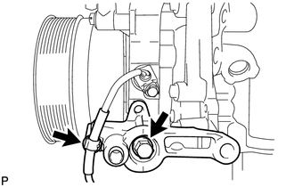
Install the chain cover and compressor bracket with the bolt.
- Torque:
- 21 N*m (214 kgf*cm, 15 ft.*lbf)
Connect the wire harness.
16630H 8.INSTALL IDLER PULLEY ASSEMBLY (w/o Air Conditioning System)
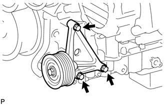
Install the idler pulley with the 3 bolts.
- Torque:
- 24.5 N*m (250 kgf*cm, 18 ft.*lbf)
17142 9.INSTALL EXHAUST MANIFOLD LH WITH TURBOCHARGER SUB-ASSEMBLY
15474A 10.INSTALL TURBO OIL OUTLET HOSE
17293 11.INSTALL TURBOCHARGER STAY
16027 12.INSTALL NO. 1 TURBO WATER PIPE SUB-ASSEMBLY
17361J 13.INSTALL NO. 1 AIR TUBE
17878 14.INSTALL NO. 3 INTAKE AIR CONNECTOR PIPE
17141 15.INSTALL EXHAUST MANIFOLD RH
17106 16.INSTALL EXHAUST CROSSOVER PIPE SUB-ASSEMBLY
17168 17.INSTALL NO. 2 EXHAUST MANIFOLD HEAT INSULATOR
Install the No. 2 exhaust manifold heat insulator with the 3 bolts.
- Torque:
- 25 N*m (255 kgf*cm, 18 ft.*lbf)
17167 18.INSTALL NO. 1 EXHAUST MANIFOLD HEAT INSULATOR
11452 19.INSTALL ENGINE OIL LEVEL DIPSTICK GUIDE
12142 20.INSTALL NO. 2 ENGINE OIL LEVEL DIPSTICK GUIDE
15301 21.INSTALL ENGINE OIL LEVEL DIPSTICK
16262 22.CONNECT WATER INLET HOSE
Connect the water inlet hose to the timing chain cover sub-assembly, and slide the clamp to secure the hose.
16331A 23.INSTALL THERMOSTAT
16321 24.INSTALL WATER INLET
16620D 25.INSTALL V-RIBBED BELT TENSIONER ASSEMBLY
16603B 26.INSTALL IDLER PULLEY SUB-ASSEMBLY
16307A 27.INSTALL FAN BRACKET SUB-ASSEMBLY
16332 28.ASSEMBLE NO. 1 AND NO. 2 WATER OUTLET PIPES AND WATER BY-PASS OUTLET SUB-ASSEMBLY
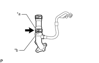
| *a | Painted Mark |
| *b | Protrusion |
Install the water hose joint to the water by-pass outlet sub-assembly, and slide the clamp to secure the hose.
- HINT:
-
Position the claws of the clamp as shown in the illustration.
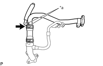
| *a | Painted Mark |
Connect the water hose joint to the No. 2 water outlet pipe, and slide the clamp to secure the hose.
- HINT:
-
Position the claws of the clamp as shown in the illustration.
Connect a new gasket and the No. 1 and No. 2 water outlet pipes with the 2 bolts.
- Torque:
- 21 N*m (214 kgf*cm, 15 ft.*lbf)
- HINT:
-
The gasket's claws can face the No. 1 or No. 2 water outlet pipe.
29.INSTALL WATER OUTLET PIPE
Temporarily install 2 new gaskets and the water outlet pipe with the 4 bolts.
Tighten the 4 bolts.
- Torque:
- 21 N*m (214 kgf*cm, 15 ft.*lbf)
16331 30.INSTALL WATER OUTLET
Connect the No. 2 water hose joint to the No. 1 water outlet pipe, and slide the clamp to secure the hose.
Install a new gasket and the water outlet with the 2 bolts.
- Torque:
- 21 N*m (214 kgf*cm, 15 ft.*lbf)
89422C 31.INSTALL ENGINE COOLANT TEMPERATURE SENSOR
Install a new gasket and the engine coolant temperature sensor.
- Torque:
- 19.6 N*m (200 kgf*cm, 14 ft.*lbf)
32.INSTALL NO. 3 ENGINE HANGER
Install the No. 3 engine hanger with the 2 bolts.
- Torque:
- 43 N*m (438 kgf*cm, 32 ft.*lbf)
17945 33.INSTALL INTERCOOLER SUPPORT BRACKET
Install the intercooler support bracket with the 2 bolts.
- Torque:
- 21 N*m (214 kgf*cm, 15 ft.*lbf)
17946 34.INSTALL NO. 2 INTERCOOLER SUPPORT BRACKET
Install the No. 2 intercooler support bracket with the 2 bolts.
- Torque:
- 43 N*m (438 kgf*cm, 32 ft.*lbf)
19850 35.INSTALL GLOW PLUG ASSEMBLY
28100 36.INSTALL STARTER ASSEMBLY
17112 37.INSTALL NO. 2 INTAKE MANIFOLD
17111 38.INSTALL INTAKE MANIFOLD
16268 39.INSTALL NO. 1 WATER BY-PASS PIPE
23920A 40.INSTALL FUEL COOLER ASSEMBLY
23763 41.CONNECT NO. 3 NOZZLE LEAKAGE PIPE
Connect the No. 1 fuel hose to the fuel cooler assembly, and slide the clamp to secure the hose.
23764A 42.INSTALL NO. 4 NOZZLE LEAKAGE PIPE
16283 43.INSTALL NO. 6 WATER BY-PASS HOSE
27020 44.INSTALL GENERATOR ASSEMBLY
27280 45.INSTALL GENERATOR SPLASH GUARD COVER ASSEMBLY
29300 46.INSTALL VACUUM PUMP ASSEMBLY
44774 47.CONNECT UNION TO CONNECTOR TUBE HOSE