1VD-FTV LUBRICATION OIL PUMP INSTALLATION
PROCEDURE

 15100 1.INSTALL OIL PUMP ASSEMBLY
Install the oil pump assembly with the 4 bolts.
- Torque:
- 10 N*m (102 kgf*cm, 7 ft.*lbf)
11381 2.CHECK REAR ENGINE OIL SEAL RETAINER
11381 3.INSTALL REAR ENGINE OIL SEAL RETAINER
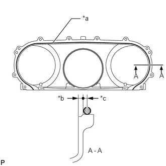
| *a | Seal Diameter: 3.0 to 5.0 mm (0.118 to 0.197 in.) |
| *b | 2.5 mm (0.0984 in.) |
| *c | 2.0 mm (0.0787 in.) |
Apply seal packing in a continuous line as shown in the illustration.
- Seal packing:
-
Toyota Genuine Seal Packing Black, Three Bond 1207B or equivalent
- NOTICE:
-
·
Remove any oil from the contact surface.
·Install the rear engine oil seal retainer within 3 minutes and tighten the bolts and nuts within 15 minutes after applying seal packing.
·Do not start the engine for at least 2 hours after installing.
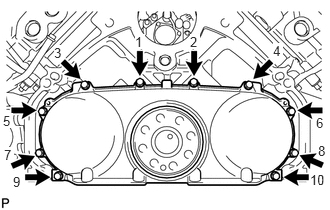
Install the rear engine oil seal retainer with the 10 bolts in the order shown in the illustration.
- Torque:
- 10 N*m (102 kgf*cm, 7 ft.*lbf)
- NOTICE:
-
·
When installing the rear engine oil seal retainer, make sure the lip of the rear crankshaft oil seal is not damaged.
·When installing the rear engine oil seal retainer, make sure the lip of the rear crankshaft oil seal is not folded incorrectly.
15310H 4.INSTALL OIL REGULATOR ASSEMBLY
Install the oil regulator assembly to the oil pump assembly with the 4 bolts.
- Torque:
- 10 N*m (102 kgf*cm, 7 ft.*lbf)
15104 5.INSTALL OIL STRAINER SUB-ASSEMBLY
Apply a light coat of engine oil to a new O-ring.
Install the O-ring to the oil strainer sub-assembly.
Install the oil strainer sub-assembly to the cylinder block with the 3 bolts.
- Torque:
- 10 N*m (102 kgf*cm, 7 ft.*lbf)
15403 6.INSTALL OUTLET OIL PUMP PIPE SUB-ASSEMBLY
Install a new O-ring and the outlet oil pump pipe sub-assembly to the oil pan sub-assembly with the 4 bolts.
- Torque:
- 10 N*m (102 kgf*cm, 7 ft.*lbf)
12101 7.CHECK OIL PAN SUB-ASSEMBLY
12101 8.INSTALL OIL PAN SUB-ASSEMBLY
Install a new cylinder block oil hole gasket to the cylinder block.
Install 2 new O-rings to the scavenging pump assembly.
- NOTICE:
-
·
Securely install the O-rings to the scavenging pump's O-ring grooves.
·Do not drop the O-ring.
Install a new O-ring to the oil regulator assembly.
- NOTICE:
-
·
Securely install the O-ring to the oil regulator assemblies O-ring groove.
·Do not drop the O-ring.
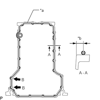
| *a | Seal Diameter: 3.5 to 4.0 mm (0.138 to 0.157 in.) |
| *b | 6.5 mm (0.256 in.) |
Apply seal packing in a continuous line as shown in the illustration.
- Seal packing:
-
Toyota Genuine Seal Packing Black, Three Bond 1207B or equivalent
- NOTICE:
-
·
For the bolt holes labeled B, apply the seal packing on the outer edges. For the other bolt holes, apply the seal packing on the inner edges.
-
·
Make sure to apply a continuous bead of seal packing as shown in the illustration. If the bead breaks, overlap 3 mm (0.118 in.) of seal packing and continue the bead.
-
·
Remove any oil from the contact surface.
·Install the oil pan sub-assembly within 3 minutes and tighten the bolts and nuts within 15 minutes after applying seal packing.
·Do not start the engine for at least 2 hours after installing.
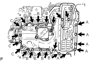
| *1 | Seal Washer |
| *a | Nut |
Install a new seal washer and the oil pan sub-assembly with the 20 bolts and 2 nuts.
- Torque:
- 24.5 N*m (250 kgf*cm, 18 ft.*lbf)
- Bolt Length:
-
Item Length Thread diameter Bolt A 30 mm (1.18 in.) 8 mm (0.315 in.) Bolt B 20 mm (0.787 in.) 8 mm (0.315 in.) Bolt C 70 mm (2.76 in.) 8 mm (0.315 in.)
9.INSTALL OIL FILTER ELEMENT
15614 10.INSTALL LOWER OIL FILTER ELEMENT COVER
Install the lower oil filter element cover to the oil pan sub-assembly with the 4 bolts.
- Torque:
- 10 N*m (102 kgf*cm, 7 ft.*lbf)
12102A 11.CHECK NO. 2 OIL PAN SUB-ASSEMBLY
12102A 12.INSTALL NO. 2 OIL PAN SUB-ASSEMBLY
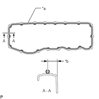
| *a | Seal Diameter: 5.0 to 6.0 mm (0.197 to 0.236 in.) |
| *b | 7.5 mm (0.295 in.) |
Apply seal packing in a continuous line as shown in the illustration.
- Seal packing:
-
Toyota Genuine Seal Packing Black, Three Bond 1207B or equivalent
- NOTICE:
-
·
For the bolt and pin holes, make sure to apply seal packing to the inner sides.
-
·
Make sure to apply a continuous bead of seal packing as shown in the illustration. If the bead breaks, overlap 3 mm (0.118 in.) of seal packing and continue the bead.
-
·
Remove any oil from the contact surface.
·Install the No. 2 oil pan sub-assembly within 3 minutes and tighten the bolts and nuts within 10 minutes after applying seal packing.
·Do not start the engine for at least 2 hours after installing.
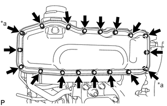
| *a | Nut |
Install the No. 2 oil pan sub-assembly to the oil pan sub-assembly with the 16 bolts and 2 nuts.
- Torque:
- 10 N*m (102 kgf*cm, 7 ft.*lbf)
17293 13.INSTALL TURBOCHARGER STAY
Install the turbocharger stay to the turbocharger and oil pan sub-assembly with the 2 bolts.
- Torque:
- 48.5 N*m (495 kgf*cm, 36 ft.*lbf)
12201 14.INSTALL VENTILATION TUBE SUB-ASSEMBLY
Install a new gasket to the union bolt.
Connect the ventilation tube sub-assembly to the oil pan sub-assembly with the union bolt.
- Torque:
- 29 N*m (296 kgf*cm, 21 ft.*lbf)
25708 15.CONNECT NO. 3 VACUUM TRANSMITTING PIPE SUB-ASSEMBLY
Connect the No. 3 vacuum transmitting pipe sub-assembly to the oil pan sub-assembly with the bolt.
- Torque:
- 6.0 N*m (61 kgf*cm, 53 in.*lbf)
Install the vacuum transmitting hose to the No. 3 vacuum transmitting pipe sub-assembly and turbocharger.
15474A 16.INSTALL OUTLET TURBO OIL HOSE
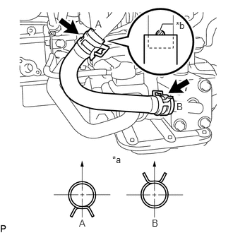
| *a | Upper |
| *b | Black Mark |
Install the oil outlet turbo oil hose and slide the 2 clamps to secure the hose as shown in the illustration.
17.INSTALL ENGINE WIRE BRACKET
Install the engine wire bracket to the cylinder block and oil pan sub-assembly with the 2 bolts.
- Torque:
- 10 N*m (102 kgf*cm, 7 ft.*lbf)
83530 18.INSTALL ENGINE OIL PRESSURE SWITCH ASSEMBLY (w/o Oil Pressure Gauge)
83520 19.INSTALL OIL PRESSURE SENDER GAUGE ASSEMBLY (w/ Oil Pressure Gauge)
15407 20.CONNECT INLET TURBO OIL PIPE SUB-ASSEMBLY
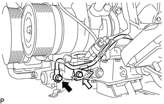

|
Union Bolt |

|
Bolt |
Install a new gasket to the union bolt.
Connect the inlet turbo oil pipe sub-assembly and install the No. 2 intake air connector bracket to the oil pan sub-assembly with the bolt and union bolt.
- Torque:
- for bolt : 21 N*m (214 kgf*cm, 15 ft.*lbf)
- for union bolt : 29 N*m (296 kgf*cm, 21 ft.*lbf)
15769 21.CONNECT OIL COOLER PIPE
Install a new gasket to the oil cooler pipe.
Connect the oil cooler pipe to the oil pan sub-assembly with the 3 bolts.
- Torque:
- 10 N*m (102 kgf*cm, 7 ft.*lbf)
22.CONNECT ENGINE WIRE
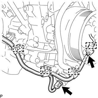
Connect the 3 engine wire connector clamps.
w/ Oil Pressure Gauge:
Connect the oil pressure sender gauge assembly connector.
w/o Oil Pressure Gauge:
Connect the engine oil pressure switch assembly connector.
Connect the crankshaft position sensor connector and connector clamp.
16620D 23.INSTALL V-RIBBED BELT TENSIONER ASSEMBLY
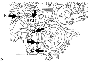
Install the V-ribbed belt tensioner assembly to the oil pan sub-assembly and timing chain cover sub-assembly with the 5 bolts.
- Torque:
- for bolt A, C : 43 N*m (438 kgf*cm, 32 ft.*lbf)
- for bolt B : 21 N*m (214 kgf*cm, 15 ft.*lbf)
- Bolt Length:
-
Item Length Thread diameter Bolt A 95 mm (3.74 in.) 10 mm (0.394 in.) Bolt B 40 mm (1.58 in.) 8 mm (0.315 in.) Bolt C 116 mm (4.57 in.) 10 mm (0.394 in.)
16603B 24.INSTALL IDLER PULLEY SUB-ASSEMBLY
Install the idler pulley sub-assembly to the V-ribbed belt tensioner assembly with the bolt.
- Torque:
- 43 N*m (438 kgf*cm, 32 ft.*lbf)
15778 25.CONNECT NO. 2 OIL COOLER HOSE
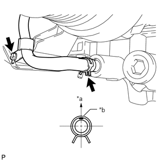
| *a | Upper |
| *b | White Mark |
Connect the No. 2 oil cooler hose to the oil pan sub-assembly, and slide the clamp to secure the hose as shown in the illustration.
Install the hose bracket to the V-ribbed belt tensioner assembly with the bolt.
- Torque:
- 10 N*m (102 kgf*cm, 7 ft.*lbf)
17878A 26.INSTALL NO. 3 INTAKE AIR CONNECTOR PIPE
Install the No. 3 intake air connector pipe to the oil pan sub-assembly with the bolt.
- Torque:
- 21 N*m (214 kgf*cm, 15 ft.*lbf)
Tighten the hose clamp bolt.
- Torque:
- 6.0 N*m (61 kgf*cm, 53 in.*lbf)
11452 27.INSTALL NO. 1 ENGINE OIL LEVEL DIPSTICK GUIDE
Apply a light coat of engine oil to a new O-ring.
Install the O-ring to the No. 1 engine oil level dipstick guide.
Install the No. 1 engine oil level dipstick guide to the oil pan sub-assembly and transverse engine mounting bracket RH with the 2 bolts.
- Torque:
- 10 N*m (102 kgf*cm, 7 ft.*lbf)
Connect the connector clamp.
12142 28.INSTALL NO. 2 ENGINE OIL LEVEL DIPSTICK GUIDE
13405 29.INSTALL FLYWHEEL SUB-ASSEMBLY
31250 30.INSTALL CLUTCH DISC ASSEMBLY
31210 31.INSTALL CLUTCH COVER ASSEMBLY
32.INSTALL MANUAL TRANSMISSION WITH TRANSFER
17875 33.INSTALL INTAKE AIR CONNECTOR PIPE
16400 34.INSTALL RADIATOR ASSEMBLY
27020 35.INSTALL GENERATOR ASSEMBLY
36.ADD ENGINE OIL
37.INSPECT FOR OIL LEAK
38.CHECK ENGINE OIL LEVEL