1GR-FE FUEL FUEL TANK(for 90 L Tank Carried in Middle) INSTALLATION
PROCEDURE

 77011 1.INSTALL FUEL TANK FILLER LOWER PIPE SUB-ASSEMBLY
Install a new gasket to the fuel tank filler lower pipe sub-assembly.
Install the fuel tank filler lower pipe sub-assembly with the 6 screws to the fuel tank assembly.
77203B 2.INSTALL FUEL SUCTION TUBE SUB-ASSEMBLY
Install a new gasket to the fuel suction tube sub-assembly.
Install the fuel suction tube sub-assembly with the 8 screws to the fuel tank assembly.
83320 3.INSTALL FUEL SENDER GAUGE ASSEMBLY
77420 4.INSTALL NO. 2 FUEL CUT OFF VALVE ASSEMBLY
Install the No. 2 fuel cut off valve assembly to the fuel tank assembly.
77380 5.INSTALL FUEL CUT OFF VALVE ASSEMBLY
Install the fuel cut off valve assembly to the fuel tank assembly.
77026A 6.INSTALL NO. 1 FUEL EVAPORATION TUBE SUB-ASSEMBLY
Install 2 new gaskets to the No. 1 fuel evaporation tube sub-assembly.
Install the No. 1 fuel evaporation tube sub-assembly with the 8 screws and 2 nuts to the fuel tank assembly.
- Torque:
- 5.5 N*m (56 kgf*cm, 49 in.*lbf)
7.INSTALL FUEL HOSE
Install the fuel inlet hose to the fuel tank filler lower pipe sub-assembly and tighten the clamp to secure the hose.
Install the fuel breather hose to the fuel tank assembly and slide the clamp to secure the hose.
Install the fuel main hose to the fuel suction tube sub-assembly .
Click hereEngine / Hybrid System>1GR-FE (FUEL)>FUEL SYSTEM>PRECAUTION
Install the fuel return hose to the fuel suction tube sub-assembly and slide the clamp to secure the hose.
Install the fuel evaporation hose to the No. 1 fuel evaporation tube sub-assembly and slide the clamp to secure the hose.
77100 8.INSTALL FUEL TANK ASSEMBLY
Set the fuel tank and No. 1 fuel tank protector sub-assembly on an engine lifter.
Raise the engine lifter.
Install the 2 fuel tank bands with the 2 pins.
Connect the 2 fuel tank bands with the 2 bolts.
- Torque:
- 39 N*m (398 kgf*cm, 29 ft.*lbf)
Attach the wire harness clamp.
Connect the fuel sender gauge connector and fuel pump connector and attach the clamp.
77100D 9.CONNECT FUEL BREATHER HOSE
Connect the fuel breather hose to the fuel tank inlet pipe sub-assembly and slide the clamp to secure the hose.
77213 10.CONNECT FUEL INLET HOSE
Connect the fuel inlet hose to the fuel tank inlet pipe sub-assembly and tighten the clamp to secure the hose.
77277R 11.INSTALL FUEL TANK FILLER PIPE PROTECTOR
Install the fuel tank filler pipe protector with the 3 bolts.
- Torque:
- 5.0 N*m (51 kgf*cm, 44 in.*lbf)
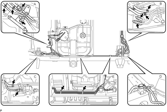
77206C 12.CONNECT NO. 2 FUEL MAIN TUBE SUB-ASSEMBLY (for Double Tank Type)
Install the No. 2 fuel main tube with the 2 bolts labeled E in the illustration.
- Torque:
- 32 N*m (326 kgf*cm, 24 ft.*lbf)
Attach the 2 fuel tube clamps labeled D in the illustration.
Connect the fuel hose and fuel main tube to the No. 2 fuel main tube sub-assembly and slide the clamp to secure the hose labeled C in the illustration.
Click hereEngine / Hybrid System>1GR-FE (FUEL)>FUEL SYSTEM>PRECAUTION
Connect the 2 fuel hoses and 2 fuel main tubes to the No. 2 fuel main tube sub-assembly and slide the 2 clamps to secure the hose labeled B in the illustration.
Click hereEngine / Hybrid System>1GR-FE (FUEL)>FUEL SYSTEM>PRECAUTION
Install the No. 1 fuel tube clamp with the bolt and attach the 3 clamps labeled A in the illustration.
- Torque:
- 32 N*m (326 kgf*cm, 24 ft.*lbf)
Connect the fuel evaporation hose to the No. 2 fuel main tube sub-assembly and slide the clamp to secure the hose labeled A in the illustration.
Connect the fuel return hose to the No. 2 fuel main tube sub-assembly and slide the clamp to secure the hose labeled A in the illustration.
Connect the fuel main tube to the No. 2 fuel main tube sub-assembly labeled A in the illustration.
Click hereEngine / Hybrid System>1GR-FE (FUEL)>FUEL SYSTEM>PRECAUTION
13.INSTALL NO. 5 FUEL TUBE PROTECTOR (for Double Tank Type)
Install the No. 5 fuel tube protector with the 2 bolts.
- Torque:
- 32 N*m (326 kgf*cm, 24 ft.*lbf)
14.INSTALL NO. 4 FUEL TUBE PROTECTOR (for Double Tank Type)
Install the No. 4 fuel tube protector with the 2 bolts.
- Torque:
- 32 N*m (326 kgf*cm, 24 ft.*lbf)
15.CONNECT FUEL HOSE AND FUEL TUBE (for Single Tank Type)
Connect the fuel main tube to the No. 2 fuel main tube sub-assembly.
Click hereEngine / Hybrid System>1GR-FE (FUEL)>FUEL SYSTEM>PRECAUTION
Connect the fuel return hose to the No. 2 fuel main tube sub-assembly and slide the clamp to secure the hose.
Connect the fuel evaporation hose to the No. 2 fuel main tube sub-assembly and slide the clamp to secure the hose.
77267A 16.INSTALL NO. 2 FUEL TUBE PROTECTOR
Install the No. 2 fuel tube protector with the 3 bolts.
- Torque:
- 32 N*m (326 kgf*cm, 24 ft.*lbf)
77266A 17.INSTALL NO. 1 FUEL TUBE PROTECTOR
37110 18.INSTALL PROPELLER SHAFT ASSEMBLY
19.SUPPORT MANUAL TRANSMISSION WITH TRANSFER
51203 20.REMOVE NO. 2 FRAME CROSSMEMBER SUB-ASSEMBLY
17410 21.INSTALL NO. 2 FRONT EXHAUST PIPE ASSEMBLY
51203 22.INSTALL NO. 2 FRAME CROSSMEMBER SUB-ASSEMBLY
51447C 23.INSTALL TRANSFER CASE PROTECTOR
24.CONNECT CABLE TO NEGATIVE BATTERY TERMINAL
25.INSPECT FOR FUEL LEAK