1VD-FTV ENGINE MECHANICAL ENGINE UNIT REASSEMBLY
CAUTION / NOTICE / HINT
- NOTICE:
-
Before performing these installation procedures, sufficiently clean and remove any foreign matter from the cylinder block sub-assembly, cylinder head sub-assembly, crankshaft, connecting rod and camshaft and other parts.
PROCEDURE

 11116 1.SELECT NO. 2 CYLINDER HEAD GASKET
11116 2.INSTALL NO. 2 CYLINDER HEAD GASKET
11102 3.INSTALL CYLINDER HEAD SUB-ASSEMBLY LH
4.INSTALL NO. 2 VALVE LASH ADJUSTER ASSEMBLY
- NOTICE:
-
Be sure to inspect the No. 2 valve lash adjuster assembly before installing it.
-
Click hereEngine / Hybrid System>1VD-FTV (ENGINE MECHANICAL)>ENGINE UNIT>INSPECTION
Install the 16 No. 2 valve lash adjuster assemblies to the cylinder head sub-assembly LH.
- HINT:
-
Install the No. 2 valve lash adjuster assembly at the same place it was removed from.
5.INSTALL NO. 2 VALVE ROCKER ARM SUB-ASSEMBLY
Apply engine oil to the No. 2 valve lash adjuster assembly tips and valve stem ends.
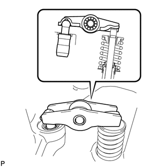
Install the 16 No. 2 valve rocker arm sub-assembly as shown in the illustration.
- HINT:
-
-
Install the No. 2 valve rocker arm sub-assemblies at the same place it was removed from.
6.INSTALL NO. 5 CAMSHAFT BEARING CAP
Align the No. 5 camshaft bearing cap and the ring pins of the cylinder head sub-assembly LH, and install the No. 5 camshaft bearing cap.
11115 7.SELECT NO. 1 CYLINDER HEAD GASKET
11115 8.INSTALL NO. 1 CYLINDER HEAD GASKET
11101 9.INSTALL CYLINDER HEAD SUB-ASSEMBLY RH
13750 10.INSTALL NO. 1 VALVE LASH ADJUSTER ASSEMBLY
- NOTICE:
-
Be sure to inspect the No. 1 valve lash adjuster assembly before installing it.
-
Click hereEngine / Hybrid System>1VD-FTV (ENGINE MECHANICAL)>ENGINE UNIT>INSPECTION
Install the 16 No. 1 valve lash adjuster assemblies to the cylinder head sub-assembly RH.
- HINT:
-
Install the No. 1 valve lash adjuster assembly at the same place it was removed from.
13801 11.INSTALL NO. 1 VALVE ROCKER ARM SUB-ASSEMBLY
Apply engine oil to the No. 1 valve lash adjuster assembly tips and valve stem ends.
Install the 16 No. 1 valve rocker arm sub-assemblies as shown in the illustration.
- HINT:
-
-
Install the No. 1 valve rocker arm sub-assembly at the same place it was removed from.
12.INSTALL NO. 2 CAMSHAFT BEARING CAP
Align the No. 2 camshaft bearing cap and the ring pins of the cylinder head sub-assembly RH, and install the No. 2 camshaft bearing cap.
13.SET NO. 1 CYLINDER TO 45° BEFORE TDC
Temporarily install the 2 crankshaft pulley set bolts to the crankshaft.
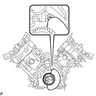
Turn the crankshaft counterclockwise until the No. 1 cylinder is at a position 45° before TDC.
- NOTICE:
-
Do not turn the crankshaft again until after the timing gear is installed.
- HINT:
-
The No. 1 cylinder is at a position 45° before TDC if the crankshaft counterweight is overlapping the cylinder block sub-assembly hole shown in the illustration.
Remove the 2 crankshaft pulley set bolts.
13511 14.INSTALL NO. 1 AND NO. 2 CAMSHAFTS
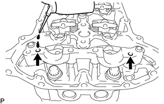
Add more than 19 cc (1.2 cu.in.) of engine oil into the cylinder head sub-assembly RH side oil holes.
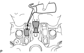
Apply engine oil to the rollers of the No. 1 valve rocker arm sub-assemblies and the camshaft housing of the cylinder head sub-assembly RH.
Install the No. 1 and No. 2 camshafts.
Apply engine oil to the camshaft journals and lobes.
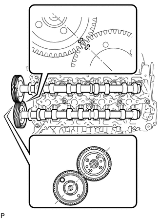
Align the timing marks (2 dot marks) on the back side of the No. 1 and No. 2 camshaft timing gears as shown in the illustration.
Place the No. 1 and No. 2 camshafts into the cylinder head sub-assembly RH.
- NOTICE:
-
-
Before and after setting the No. 1 and No. 2 camshafts, firmly set the No. 1 valve rocker arm sub-assemblies to the No. 1 valve lash adjuster assemblies.
Install the No. 1 camshaft bearing cap.
Align the No. 1 camshaft bearing cap and the ring pins of the No. 2 camshaft bearing cap.
Temporarily install the 4 bolts by hand.
Install the No. 3 camshaft bearing caps.
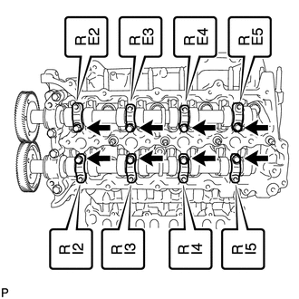
Confirm the marks and numbers on the camshaft bearing caps and place them in their proper position and direction.
Temporarily install the 8 bolts, which are not installed with the camshaft oil feed pipe sub-assemblies, by hand.
Temporarily install the No. 1 and No. 2 camshaft oil feed pipe sub-assemblies with the 8 bolts and 2 union bolts by hand.
- NOTICE:
-
If even one of the camshaft oil feed pipe sub-assembly bolt holes does not match its camshaft bearing cap bolt hole, replace the camshaft oil feed pipe sub-assembly.
- HINT:
-
The pipe is bent on the intake side, and straight on the exhaust side.
Temporarily install the 2 union bolts by hand.
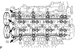

|
12 mm Head Bolt |

|
10 mm Head Bolt |
Uniformly tighten the 20 bolts in several steps in the order shown in the illustration.
- Torque:
- for 12 mm head bolt of No. 1 camshaft bearing cap : 21 N*m (214 kgf*cm, 15 ft.*lbf)
- for 10 mm head bolt of No. 3 camshaft bearing cap : 10 N*m (102 kgf*cm, 7 ft.*lbf)
Tighten the 2 union bolts.
- Torque:
- 17 N*m (173 kgf*cm, 13 ft.*lbf)
Remove the service bolt from the No. 1 camshaft timing gear.
- NOTICE:
-
Do not drop the service bolt into the engine.
13053 15.INSTALL NO. 3 AND NO. 4 CAMSHAFTS
Add more than 19 cc (1.2 cu.in.) of engine oil into the cylinder head sub-assembly LH side oil holes.
Apply engine oil to the rollers of the No. 2 valve rocker arm sub-assemblies and the camshaft housing of the cylinder head sub-assembly LH.
Install the No. 3 and No. 4 camshafts.
Apply engine oil to the camshaft journals and lobes.
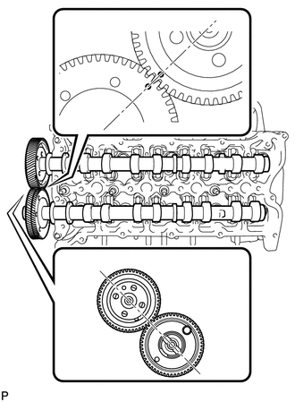
Align the timing marks (1 dot mark) on the back side of the No. 3 and No. 4 camshaft timing gears as shown in the illustration.
Place the No. 3 and No. 4 camshafts into the cylinder head sub-assembly LH.
- NOTICE:
-
-
Before and after setting the No. 3 and No. 4 camshafts, firmly set the No. 2 valve rocker arm sub-assemblies to the No. 2 valve lash adjuster assemblies.
Install the No. 4 camshaft bearing cap.
Align the No. 4 camshaft bearing cap and the ring pins of the No. 5 camshaft bearing cap.
Temporarily install the 4 bolts by hand.
Install the No. 3 camshaft bearing caps.
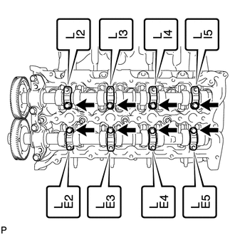
Confirm the marks and numbers on the camshaft bearing caps and place them in their proper position and direction.
Temporarily install the 8 bolts, which are not installed with the camshaft oil feed pipe sub-assemblies, by hand.
Temporarily install the No. 3 and No. 4 camshaft oil feed pipe sub-assemblies with the 8 bolts and 2 union bolts by hand.
- NOTICE:
-
If even one of the camshaft oil feed pipe sub-assembly bolt holes does not match its camshaft bearing cap bolt hole, replace the camshaft oil feed pipe sub-assembly.
- HINT:
-
The pipe is bent on the intake side, and straight on the exhaust side.
Temporarily install the 2 union bolts.
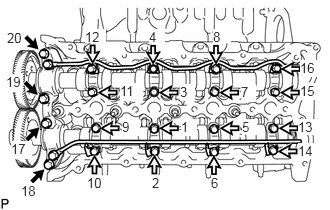
|
|
12 mm Head Bolt |
|
|
10 mm Head Bolt |
Uniformly tighten the 20 bolts in several steps in the order shown in the illustration.
- Torque:
- for 12 mm head bolt of No. 4 camshaft bearing cap : 21 N*m (214 kgf*cm, 15 ft.*lbf)
- for 10 mm head bolt of No. 3 camshaft bearing cap : 10 N*m (102 kgf*cm, 7 ft.*lbf)
Tighten the 2 union bolts.
- Torque:
- 17 N*m (173 kgf*cm, 13 ft.*lbf)
Remove the service bolt from the No. 4 camshaft timing gear.
- NOTICE:
-
Do not drop the service bolt into the engine.
25707 16.INSTALL NO. 2 VACUUM TRANSMITTING PIPE SUB-ASSEMBLY
Install the No. 2 vacuum transmitting pipe sub-assembly with the 3 bolts.
- Torque:
- 6.0 N*m (61 kgf*cm, 53 in.*lbf)
17.INSTALL STUD BOLT
- HINT:
-
If the stud bolt is deformed or the threads are damaged, replace it.
Using an E7 "TORX" wrench, install the 4 stud bolts labeled A.
- Torque:
- 6.0 N*m (61 kgf*cm, 53 in.*lbf)
Install the 2 stud bolts labeled B.
- Torque:
- 10 N*m (102 kgf*cm, 7 ft.*lbf)
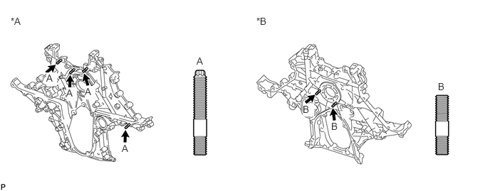
| *A | for Front Side | *B | for Rear Side |
11301 18.INSTALL TIMING GEAR CASE SUB-ASSEMBLY
- NOTICE:
-
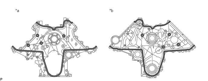
When the contact surfaces shown below are wet, wipe them with an oil-free cloth before applying seal packing.
-
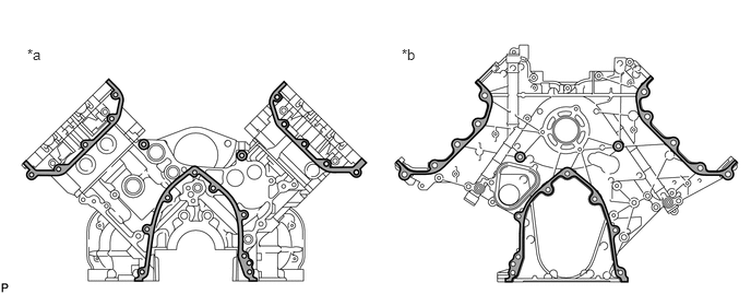 0.26,0.438 0.573,0.594 0.313,0.156 10 false *a 3.833,0.438 4.146,0.594 0.313,0.156 10 false *b
*a Cylinder Block Sub-assembly Side *b Timing Gear Case Sub-assembly Side
Apply seal packing to the timing gear case sub-assembly as shown in the following illustration.
- Standard seal diameter:
-
4.0 to 5.0 mm (0.158 to 0.197 in.)
- Seal packing:
-
Toyota Genuine Seal Packing Black, Three Bond 1207B or equivalent
- NOTICE:
-
·
After applying seal packing, align the timing gear case sub-assembly with the engine within 3 minutes and tighten the bolts and nuts within 15 minutes.
·Apply the seal packing in a continuous line.
- HINT:
-
·
The FIPG line is shown below.
·Apply packing to the 5 seal surface areas.
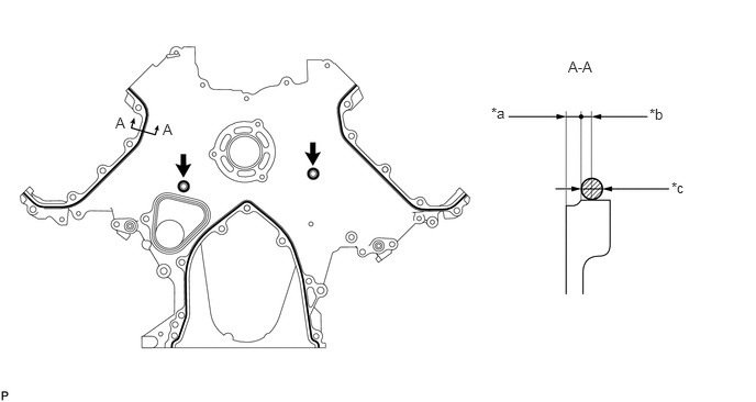
| *a | 2.5 mm (0.0984 in.) | *b | 2.0 mm (0.0787 in.) |
| *c | Seal Diameter: 4.0 to 5.0 mm (0.158 to 0.197 in.) | - | - |
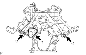
| *1 | Timing Gear Case Sub-assembly Gasket |
| *2 | O-Ring |
Install a new timing gear case sub-assembly gasket.
Apply engine oil to 2 new O-rings and install them to the timing gear case sub-assembly.
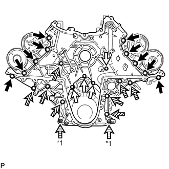
| *1 | Nut |
|
|
14 mm Head Bolt |
|
|
12 mm Head Bolt A |

|
12 mm Head Bolt B |
Install the timing gear case sub-assembly with the 22 bolts and 2 nuts.
- Torque:
- for 14 mm head bolt (When "dry") : 46 N*m (469 kgf*cm, 34 ft.*lbf)
- for 14 mm head bolt (When "wet") : 42 N*m (428 kgf*cm, 31 ft.*lbf)
- for 12 mm head bolt A and B : 29 N*m (296 kgf*cm, 21 ft.*lbf)
- for nut : 29 N*m (296 kgf*cm, 21 ft.*lbf)
- Bolt Length:
-
Item Quantity Length A 4 20 mm (0.787 in.) B 8 45 mm (1.77 in.)
- NOTICE:
-
·
The case is "dry" when there is absolutely no engine oil on the 14 mm head bolts and cylinder head set bolt holes.
·The case is "wet" when there is engine oil on the 14 mm head bolts and cylinder head set bolt holes.
11248 19.INSTALL V-BANK SILENCER
Align the alignment areas of the V-bank silencer and cylinder block sub-assembly, and install the V-bank silencer.
- NOTICE:
-
Verify that the V-bank silencer is below the top surface of the intake port of the cylinder head sub-assembly RH and LH.
22100 20.INSTALL FUEL SUPPLY PUMP ASSEMBLY
21.INSTALL STRAIGHT PIN
- HINT:
-
It is not necessary to remove the straight pin unless it is being replaced.
Install the straight pin.
- Standard protrusion height:
-
4.5 to 7.0 mm (0.177 to 0.276 in.)
13616 22.ASSEMBLE INJECTION PUMP DRIVE GEAR AND INJECTION PUMP SHAFT SPROCKET SUB-ASSEMBLY
Temporarily install and align the injection pump drive gear to the straight pin with the 4 bolts.
Hold the injection pump shaft sprocket sub-assembly in a vise between aluminum plates.
- NOTICE:
-
Be careful not to damage the injection pump drive gear.
Tighten the 4 bolts.
- Torque:
- 24.5 N*m (250 kgf*cm, 18 ft.*lbf)
23.INSTALL RADIAL BALL BEARING
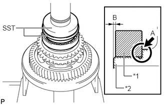
| *1 | Radial Ball Bearing |
| *2 | Injection Pump Shaft Sprocket Sub-assembly |
Using SST and a press, press in the radial ball bearing to the injection pump shaft sprocket sub-assembly.
- SST
-
09316-12010
09950-60010 (09951-00580)
- NOTICE:
-
·
Make sure to press in the radial ball bearing until the radial ball bearing contacts the injection pump shaft sprocket sub-assembly as shown in A in the illustration.
·Make sure the injection pump shaft sprocket sub-assembly outer edge is further outward than the radial ball bearing outer edge as shown in B in the illustration.
13613 24.TEMPORARILY INSTALL INJECTION PUMP DRIVE GEAR
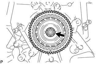
Align the cutout of the injection pump drive gear and key of the fuel supply pump assembly, and temporarily install the injection pump drive gear nut.
25.SET NO. 1 AND NO. 2 CAMSHAFTS TO TDC/COMPRESSION
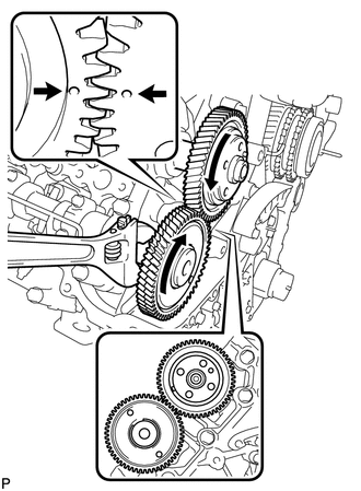
Using a wrench, turn the No. 1 camshaft and align the timing marks (1 dot mark) on the back side of the camshaft timing gears as shown in the illustration.
13581 26.INSTALL NO. 1 IDLE GEAR SHAFT
Apply engine oil to the contact surface of the No. 1 idle gear shaft.
Install the No. 1 idle gear shaft to the cylinder block sub-assembly.
13525 27.INSTALL NO. 1 IDLE GEAR
Temporarily install the 2 crankshaft pulley set bolts to the crankshaft.
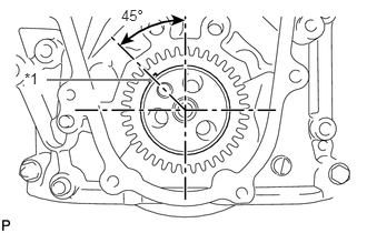
| *1 | Key |
Using a bar, turn the crankshaft clockwise to the No. 1 cylinder TDC position.
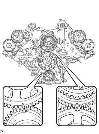
Align the timing marks of the injection pump drive gear and No. 1 idle gear, and the timing marks of the crankshaft timing gear and No. 1 idle gear as shown in the illustration.
Apply engine oil to the idle gear thrust plate.
Install the idle gear thrust plate with the 2 bolts.
- Torque:
- 47 N*m (479 kgf*cm, 35 ft.*lbf)
28.TIGHTEN INJECTION PUMP DRIVE GEAR NUT
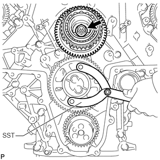
Using SST, hold the No. 1 idle gear and tighten the injection pump drive gear nut.
- SST
-
09960-10010 (09962-01000, 09963-01000)
- Torque:
- 68 N*m (693 kgf*cm, 50 ft.*lbf)
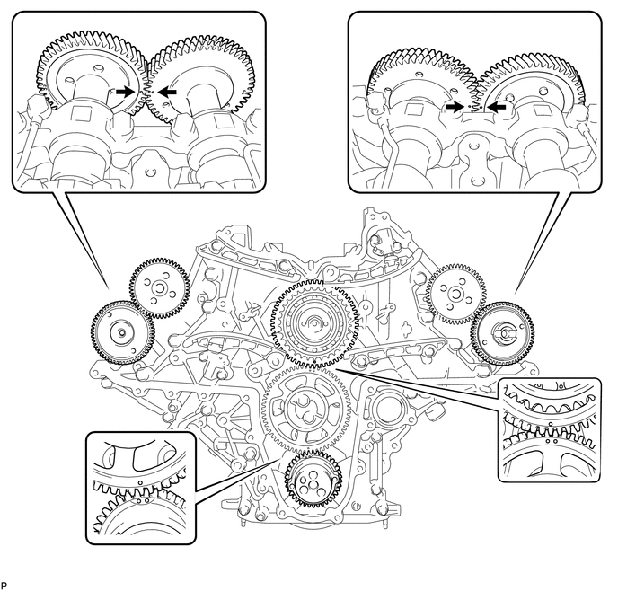
29.CHECK NO. 1 CYLINDER AT TDC/COMPRESSION
Check that the timing marks of the following pairs of parts are aligned: 1) injection pump drive gear and No. 1 idle gear, 2) crankshaft timing gear and No. 1 idle gear, 3) RH and LH camshaft timing gears.
13529G 30.INSTALL NO. 2 CAMSHAFT TIMING SPROCKET AND NO. 2 CHAIN SUB-ASSEMBLY
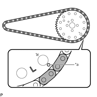
| *a | Timing Mark |
Align the 2 mark plates (yellow) on the No. 2 chain sub-assembly with the timing mark (1 dot mark) of the No. 2 camshaft timing sprocket shown in the illustration.
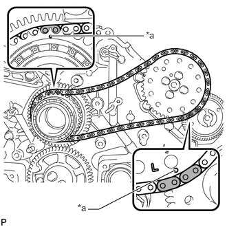
| *a | Timing Mark |
Align the No. 2 chain sub-assembly plate (yellow) with the injection pump drive gear timing mark, and temporarily install the No. 2 camshaft timing sprocket with the 4 bolts.
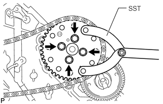
Using SST, hold the No. 2 camshaft timing sprocket and tighten the 4 bolts.
- SST
-
09960-10010 (09962-01000, 09963-01000)
- Torque:
- 24.5 N*m (250 kgf*cm, 18 ft.*lbf)
13523 31.INSTALL NO. 1 CAMSHAFT TIMING SPROCKET AND NO. 1 CHAIN SUB-ASSEMBLY
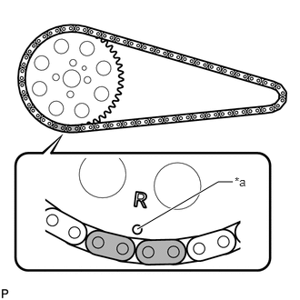
| *a | Timing Mark |
Align the 2 mark plates (yellow) on the No. 1 chain sub-assembly with the timing mark (1 dot mark) of the No. 1 camshaft timing sprocket shown in the illustration.
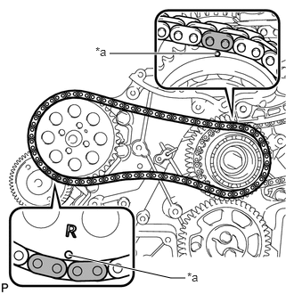
| *a | Timing Mark |
Align the No. 1 chain sub-assembly plate (yellow) with the injection pump drive gear timing mark, and temporarily install the No. 1 camshaft timing sprocket.
13522 32.INSTALL PUMP DRIVE SHAFT GEAR
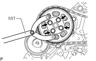
Temporarily install the pump drive shaft gear with the 4 bolts.
Using SST, hold the pump drive shaft gear and tighten the 4 bolts.
- SST
-
09960-10010 (09962-01000, 09963-01000)
- Torque:
- 24.5 N*m (250 kgf*cm, 18 ft.*lbf)
33.INSTALL NO. 2 CHAIN VIBRATION DAMPER
Install the No. 2 chain vibration damper with the 2 bolts.
- Torque:
- 21 N*m (214 kgf*cm, 15 ft.*lbf)
34.INSTALL NO. 2 CHAIN TENSIONER SLIPPER
35.INSTALL NO. 2 CHAIN TENSIONER ASSEMBLY
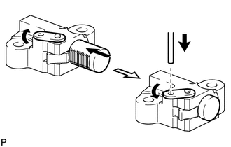
Move the stopper plate clockwise to release the lock, and push the plunger into the No. 2 chain tensioner assembly.
Move the stopper plate counterclockwise to set the lock, and insert a hexagon wrench into the stopper plate hole.
Install the No. 2 chain tensioner assembly with the 2 bolts.
- Torque:
- 10 N*m (102 kgf*cm, 7 ft.*lbf)
Remove the hexagon wrench.
13561 36.INSTALL NO. 1 CHAIN VIBRATION DAMPER
Install the No. 1 chain vibration damper with the 2 bolts.
- Torque:
- 21 N*m (214 kgf*cm, 15 ft.*lbf)
13559 37.INSTALL NO. 1 CHAIN TENSIONER SLIPPER
13540 38.INSTALL NO. 1 CHAIN TENSIONER ASSEMBLY
Move the stopper plate clockwise to release the lock, and push the plunger into the No. 1 chain tensioner assembly.
Move the stopper plate counterclockwise to set the lock, and insert a hexagon wrench into the stopper plate hole.
Install the No. 1 chain tensioner assembly with the 2 bolts.
- Torque:
- 10 N*m (102 kgf*cm, 7 ft.*lbf)
Remove the hexagon wrench.
19315 39.INSTALL NO. 1 CRANKSHAFT POSITION SENSOR PLATE
Remove the adhesive from the threads of the 2 screws and the bolt holes of the crankshaft.
Apply adhesive to 2 or 3 threads of the 2 screws.
- Adhesive:
-
Toyota Genuine Adhesive 1344, Three Bond 1344 or equivalent
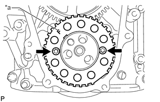
| *a | "F" Mark |
Using a T30 "TORX" wrench, install the No. 1 crankshaft position sensor plate with the 2 screws.
- Torque:
- 10 N*m (102 kgf*cm, 7 ft.*lbf)
- NOTICE:
-
Make sure the "F" mark on the plate is facing towards the front side of the engine.
40.CHECK NO. 1 CYLINDER AT TDC/COMPRESSION
Temporarily install the 2 crankshaft pulley set bolts to the crankshaft.
Rotate the crankshaft 2 revolutions or more so that the crankshaft key is 45° counterclockwise from the top. Check that the timing marks (1 dot mark each) of the RH and LH camshaft timing gears align. If not as specified, turn the crankshaft 1 revolution (360°) and align the timing marks. If the timing marks are deviated, reinstall the chain sub-assembly and camshaft.
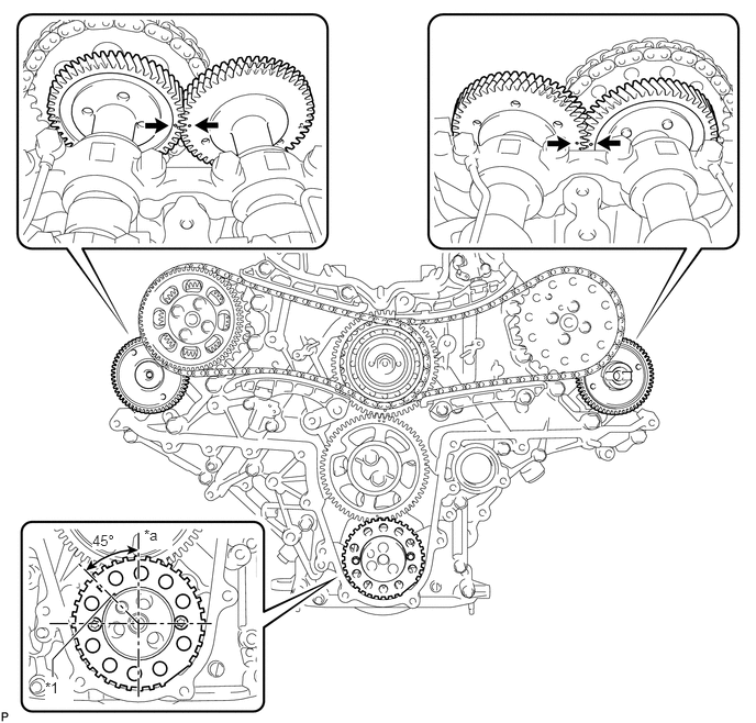
| *1 | Key | - | - |
| *a | Top | - | - |
Remove the 2 crankshaft pulley set bolts.
11302A 41.INSTALL FRONT CRANKSHAFT OIL SEAL
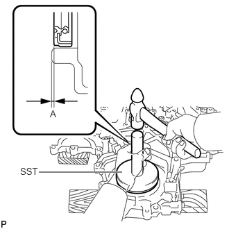
Place the timing chain cover sub-assembly on wooden blocks.
Using SST and hammer, tap in a new front crankshaft oil seal as shown in the illustration.
- SST
-
09316-12010
09950-70010 (09951-07100)
09950-60020 (09951-00890)
- Standard depth A:
-
0.6 to 1.4 mm (0.0236 to 0.0551 in.)
11302 42.INSTALL TIMING CHAIN COVER SUB-ASSEMBLY
- NOTICE:
-
When the contact surfaces shown below are wet, wipe them with an oil-free cloth before applying seal packing.
-
 0.531,0.281 0.844,0.438 0.313,0.156 10 false *a 3.771,0.281 4.083,0.438 0.313,0.156 10 false *b
*a Timing Gear Case Sub-assembly Side *b Timing Chain Cover Sub-assembly Side
Install a new O-ring to the timing gear case sub-assembly.
Apply seal packing to the timing chain cover sub-assembly shown in the following illustration.
- Standard seal diameter:
-
4.0 to 5.0 mm (0.158 to 0.197 in.)
- Seal packing:
-
Toyota Genuine Seal Packing Black, Three Bond 1207B or equivalent
- NOTICE:
-
·
After applying seal packing, align the timing chain cover sub-assembly with the timing gear case sub-assembly within 3 minutes and tighten the bolts and nuts within 15 minutes.
·Apply the seal packing in a continuous line.
·Make sure the seal packing does not become thinner than 4.0 mm (0.158 in.) at the areas labeled "B" in the illustration below.
- HINT:
-
·
The FIPG line is shown below.
·Apply packing to the 6 seal surface areas.
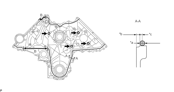
| *a | Seal Diameter: 4.0 to 5.0 mm (0.158 to 0.197 in.) | *b | 2.5 mm (0.0984 in.) |
| *c | 2.0 mm (0.0787 in.) | - | - |
Apply engine oil to the lip of the front crankshaft oil seal.
Align and install the timing chain cover sub-assembly to the timing gear case sub-assembly knock pin and fuel supply pump assembly bearing.
- NOTICE:
-
Make sure that the lip of the front crankshaft oil seal is properly installed.
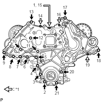
| *1 | Nut |
Install and uniformly tighten the 16 bolts and 4 nuts in the order shown in the illustration.
- Torque:
- 24.5 N*m (250 kgf*cm, 18 ft.*lbf)
13471 43.INSTALL CRANKSHAFT PULLEY
Align the crankshaft pulley and the crankshaft knock pin.
Temporarily install the 3 bolts.
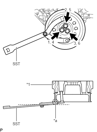
| *1 | Crankshaft Pulley |
| *a | Protective Tape |
Using SST, hold the crankshaft pulley.
- SST
-
09960-10010 (09962-01000, 09963-01000)
- NOTICE:
-
To prevent damage to the crankshaft pulley, apply protective tape to the contact areas of SST and the crankshaft pulley before performing this procedure.
Install and uniformly tighten the 3 bolts in 2 passes in the order shown in the illustration.
- Torque:
- 114.5 N*m (1168 kgf*cm, 84 ft.*lbf)
17112 44.TEMPORARILY INSTALL NO. 2 INTAKE MANIFOLD
Install the gasket and temporarily install the No. 2 intake manifold.
17111 45.TEMPORARILY INSTALL INTAKE MANIFOLD
Install the gasket and temporarily install the intake manifold.
17114D 46.TEMPORARILY INSTALL NO. 3 INTAKE MANIFOLD
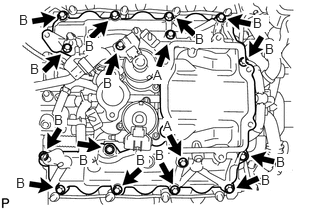
Install the gasket and temporarily install the No. 3 intake manifold.
- Bolt Length:
-
Item Length Bolt A 70 mm (2.76 in.) Bolt B 25 mm (0.984 in.)
23670 47.INSTALL INJECTOR ASSEMBLY LH (w/o DPF)
23670 48.INSTALL INJECTOR ASSEMBLY RH (w/o DPF)
- NOTICE:
-
Be sure to install the injector assembly, No. 1 nozzle holder clamp and bolt in their original positions.
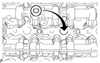
Install 4 new injection nozzle seats to the cylinder head sub-assembly RH.
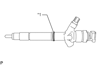
| *1 | O-Ring |
Apply a light coat of clean engine oil to 4 new O-rings.
Install an O-ring to each injector assembly as shown in the illustration.
Insert the 4 injector assemblies into the cylinder head sub-assembly RH.
- NOTICE:
-
·
Insert the injector assembly until it touches the injection nozzle seat surface.
·After installing the injector assembly to the cylinder head sub-assembly RH, the O-ring may prevent the injector assembly from fully seating. If so, pull out the injector assembly and reinstall it.
·Always return an injector assembly to the same place it was removed from.
For an injector assembly that has been replaced with a new injector assembly, register the injector assembly compensation code.
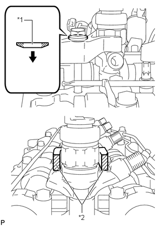
| *1 | Washer |
| *2 | No. 1 Nozzle Holder Clamp |
|
|
Downward |
Temporarily install 4 new washers and the 4 No. 1 nozzle clamps with the 4 bolts.
- NOTICE:
-
·
The fork portion of the No. 1 nozzle holder clamp must be set to the injector assembly.
·Before tightening the bolts, check that the No. 1 nozzle holder clamp is set properly.
·To fasten the bolts, first tighten them by hand until they cannot be turned further. Then, tighten the bolts to the specified torque in a later step.
·When tightening the bolts, pay attention not to tilt the bolt and No. 1 nozzle holder clamp.
·Do not reuse the washer.
Temporarily install the common rail assembly RH with the 2 bolts.
Temporarily install the 4 injection pipe sub-assemblies to the common rail assembly and injector assembly.
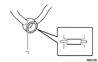
| *1 | No. 2 Nozzle Leakage Pipe |
Check the No. 2 nozzle leakage pipe. Check that there are no scratches or dents on the 5 union seal surfaces. If scratches or dents are present, replace the No. 2 nozzle leakage pipe.
Set the No. 2 nozzle leakage pipe and 5 new gaskets in place.
Temporarily install the No. 2 leakage pipe with the 4 injector hollow screws and union bolt.
- HINT:
-
To position the injector assemblies, loosely tighten the 4 injector hollow screws and union bolt.
Tighten the 4 bolts.
- Torque:
- 25 N*m (255 kgf*cm, 18 ft.*lbf)
Remove the 4 injection pipe sub-assemblies.
Remove the 2 bolts and common rail assembly RH.
Tighten the 4 injector hollow screws.
- Torque:
- 18 N*m (184 kgf*cm, 13 ft.*lbf)
- NOTICE:
-
If an injector hollow screw is accidentally tightened beyond the torque specification, it must be replaced.
Tighten the union bolt.
- Torque:
- 21 N*m (214 kgf*cm, 15 ft.*lbf)
- NOTICE:
-
If the union bolt is accidentally tightened beyond the torque specification, it must be replaced.
11239 49.INSTALL NO. 4 CYLINDER HEAD COVER GASKET (w/ DPF)
Install a new No. 4 cylinder head cover gasket to the cylinder head cover sub-assembly RH.
- NOTICE:
-
Remove any oil from the contact surface.
11229 50.INSTALL NO. 3 CYLINDER HEAD COVER GASKET (w/ DPF)
Install a new No. 3 cylinder head cover gasket to the cylinder head cover sub-assembly LH.
- NOTICE:
-
Remove any oil from the contact surface.
11213 51.INSTALL CYLINDER HEAD COVER GASKET
Install 2 new cylinder head cover gaskets to the cylinder head cover sub-assembly.
- NOTICE:
-
Remove any oil from the contact surface.
11202 52.INSTALL CYLINDER HEAD COVER SUB-ASSEMBLY LH (w/ DPF)
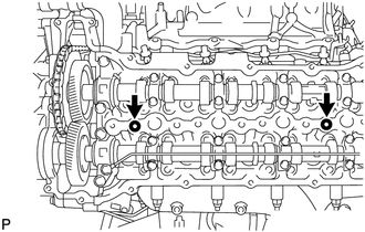
Temporarily install 2 service stud bolts (8 mm x 1.25 pitch with a length of 30 mm or more) to the 2 locations shown in the illustration.
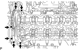
|
|
Seal Packing |
Apply seal packing as shown in the illustration.
- Seal packing:
-
Toyota Genuine Seal Packing Black, Three Bond 1207B or equivalent
- NOTICE:
-
·
Remove any oil from the contact surface.
·Install the cylinder head cover sub-assembly LH within 3 minutes and tighten the bolts within 15 minutes after applying seal packing.
·Do not start the engine for at least 2 hours after the installation.
Using the service stud bolts as guides, place the cylinder head cover sub-assembly LH on the cylinder head sub-assembly.
Remove the 2 service stud bolts.
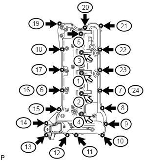
|
|
Bolt |
|
|
Nozzle Holder Clamp Seat |
Temporarily install the cylinder head cover sub-assembly LH with the 18 bolts and 4 nozzle holder clamp seats. Tighten the 18 bolts and 4 nozzle holder clamp seats in the order shown in the illustration.
- Torque:
- 10 N*m (102 kgf*cm, 7 ft.*lbf)
- HINT:
-
After tightening the bolts, check that the bolts at step 16 and 24 are tightened to the specified torque.
11201 53.INSTALL CYLINDER HEAD COVER SUB-ASSEMBLY RH (w/ DPF)
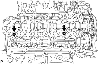
Temporarily install 2 service stud bolts (8 mm x 1.25 pitch with a length of 30 mm or more) to the 2 locations shown in the illustration.
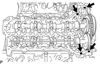
|
|
Seal Packing |
Apply seal packing as shown in the illustration.
- Seal packing:
-
Toyota Genuine Seal Packing Black, Three Bond 1207B or equivalent
- NOTICE:
-
·
Remove any oil from the contact surface.
·Install the cylinder head cover sub-assembly RH within 3 minutes and tighten the bolts within 15 minutes after applying seal packing.
·Do not start the engine for at least 2 hours after the installation.
Using the service stud bolts as guides, place the cylinder head cover sub-assembly RH on the cylinder head sub-assembly.
Remove the 2 service stud bolts.
|
|
Bolt |
|
|
Nozzle Holder Clamp Seat |
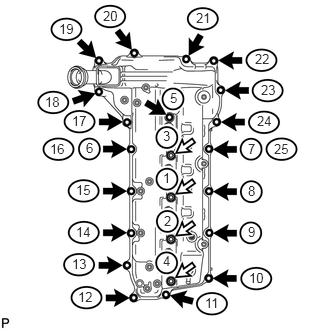
Temporarily install the cylinder head cover sub-assembly RH with the 19 bolts and 4 nozzle holder clamp seats. Tighten the 19 bolts and 4 nozzle holder clamp seats in the order shown in the illustration.
- Torque:
- 10 N*m (102 kgf*cm, 7 ft.*lbf)
- HINT:
-
After tightening the bolts, check that the bolts at step 16 and 25 are tightened to the specified torque.
23670 54.INSTALL INJECTOR ASSEMBLY LH (w/ DPF)
23670 55.INSTALL INJECTOR ASSEMBLY RH (w/ DPF)
17114D 56.REMOVE NO. 3 INTAKE MANIFOLD
Remove the 16 bolts, No. 3 intake manifold and 2 gaskets.
17111 57.REMOVE INTAKE MANIFOLD
Remove the 9 bolts, intake manifold and gasket.
17112 58.REMOVE NO. 2 INTAKE MANIFOLD
Remove the 9 bolts, No. 2 intake manifold and gasket.
23682B 59.INSTALL NOZZLE HOLDER GASKET LH (w/o DPF)
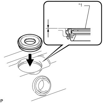
| *1 | Nozzle Holder Gasket |
Press 4 new nozzle holder gaskets into the cylinder head cover sub-assembly LH.
- NOTICE:
-
After installing the nozzle holder gasket LH, check that it does not protrude from the cylinder head cover sub-assembly LH.
23682A 60.INSTALL NOZZLE HOLDER GASKET RH (w/o DPF)
| *1 | Nozzle Holder Gasket |
Press 4 new nozzle holder gaskets into the cylinder head cover sub-assembly RH.
- NOTICE:
-
After installing the nozzle holder gasket, check that it does not protrude from the cylinder head cover sub-assembly RH.
11202 61.INSTALL CYLINDER HEAD COVER SUB-ASSEMBLY LH (w/o DPF)
12270 62.INSTALL OIL SEPARATOR ASSEMBLY
11201 63.INSTALL CYLINDER HEAD COVER SUB-ASSEMBLY RH (w/o DPF)
12108A 64.INSTALL OIL FILLER CAP GASKET
Install the oil filler cap gasket to the oil filler cap sub-assembly.
12108 65.INSTALL OIL FILLER CAP SUB-ASSEMBLY
23681D 66.INSTALL NOZZLE HOLDER SEAL RH (w/o DPF)
23681E 67.INSTALL NOZZLE HOLDER SEAL LH (w/o DPF)
151A0 68.INSTALL SCAVENGING PUMP ASSEMBLY
15100 69.INSTALL OIL PUMP ASSEMBLY
11381A 70.INSTALL REAR CRANKSHAFT OIL SEAL
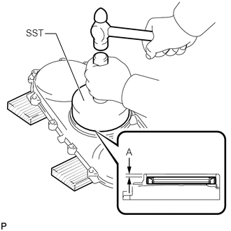
Place the engine rear oil seal retainer on wooden blocks.
Apply engine oil to the lip of a new rear crankshaft oil seal.
Using SST and a hammer, tap in the rear crankshaft oil seal as shown in the illustration.
- SST
-
09223-56010
- Standard depth A:
-
2.7 to 3.7 mm (0.106 to 0.146 in.)
- NOTICE:
-
·
Keep the lip free from foreign matter.
·Do not tap on the rear crankshaft oil seal at an angle.
11381 71.CHECK ENGINE REAR OIL SEAL RETAINER
- NOTICE:
-
When the contact surfaces shown below are wet, wipe them with an oil-free cloth before applying seal packing.
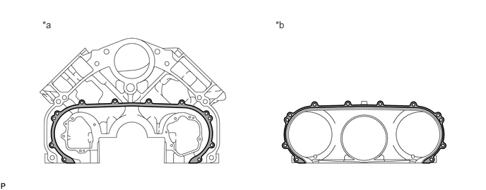
| *a | Cylinder Block Sub-assembly Side | *b | Engine Rear Oil Seal Retainer Side |
11381 72.INSTALL ENGINE REAR OIL SEAL RETAINER
15310H 73.INSTALL OIL REGULATOR ASSEMBLY
15104 74.INSTALL OIL STRAINER SUB-ASSEMBLY
75.INSTALL STUD BOLT
- HINT:
-
If the stud bolt is deformed or the threads are damaged, replace it.
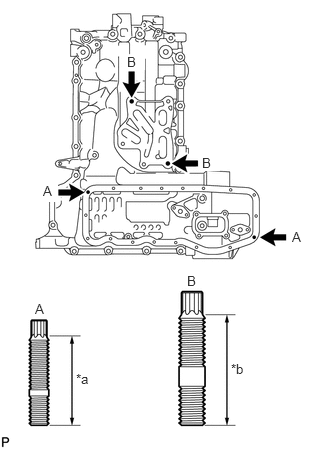
| *a | 27 mm (1.063 in.) |
| *b | 34 mm (1.34 in.) |
Using an E6 "TORX" wrench, install the 2 stud bolts labeled A.
- Torque:
- 5.2 N*m (53 kgf*cm, 46 in.*lbf)
Using an E8 "TORX" wrench, install the 2 stud bolts labeled B.
- Torque:
- 7.5 N*m (76 kgf*cm, 66 in.*lbf)
11432T 76.INSTALL STRAIGHT SCREW PLUG
- HINT:
-
If water leaks from the straight screw plug or the straight screw plug is corroded, replace the straight screw plug.
Using a 10 mm hexagon wrench, install a new gasket and the straight screw plug.
- Torque:
- 50 N*m (510 kgf*cm, 37 ft.*lbf)
Using a 14 mm hexagon wrench, install 2 new gaskets and the 2 straight screw plugs.
- Torque:
- 86 N*m (877 kgf*cm, 63 ft.*lbf)
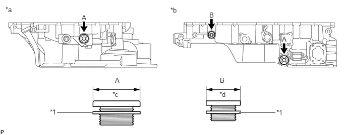
| *1 | Gasket | - | - |
| *a | Front Side of Oil Pan Sub-assembly | *b | LH Side of Oil Pan Sub-assembly |
| *c | 37 mm (1.46 in.) | *d | 27 mm (1.06 in.) |
15479 77.INSTALL TURBO OIL PIPE FLANGE
Install the turbo oil pipe flange with the 2 bolts.
- Torque:
- 10 N*m (102 kgf*cm, 7 ft.*lbf)
15403 78.INSTALL OIL PUMP OUTLET PIPE SUB-ASSEMBLY
15777K 79.INSTALL OIL COOLER HOSE DRAIN COCK ASSEMBLY
Apply adhesive to 2 or 3 threads of the oil cooler hose drain cock assembly.
- Adhesive:
-
Toyota Genuine Adhesive 1344, Three Bond 1344 or equivalent
Using a 17 mm wrench, install the oil cooler hose drain cock assembly.
- Torque:
- 20 N*m (204 kgf*cm, 15 ft.*lbf)
12121 80.INSTALL NO. 1 OIL PAN BAFFLE PLATE
Install the No. 1 oil pan baffle plate with the 5 bolts.
- Torque:
- 10 N*m (102 kgf*cm, 7 ft.*lbf)
12101 81.CHECK OIL PAN SUB-ASSEMBLY
- NOTICE:
-
When the contact surfaces shown below are wet, wipe them with an oil-free cloth before applying seal packing.
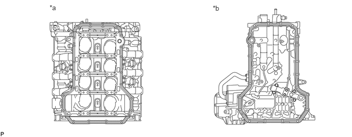
| *a | Cylinder Block Sub-assembly Side | *b | Oil Pan Sub-assembly Side |
12101 82.INSTALL OIL PAN SUB-ASSEMBLY
15769 83.CONNECT OIL COOLER PIPE
15614 84.INSTALL LOWER OIL FILTER ELEMENT COVER
151C1 85.INSTALL SCAVENGING PUMP PIPE
Install 2 new gaskets and the scavenging pump pipe with the 4 bolts.
- Torque:
- 10 N*m (102 kgf*cm, 7 ft.*lbf)
12102A 86.CHECK NO. 2 OIL PAN SUB-ASSEMBLY
- NOTICE:
-
When the contact surfaces shown below are wet, wipe them with an oil-free cloth before applying seal packing.
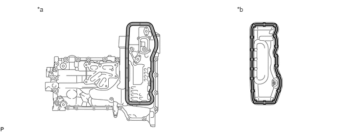
| *a | Oil Pan Sub-assembly Side | *b | No. 2 Oil Pan Sub-assembly Side |
12102A 87.INSTALL NO. 2 OIL PAN SUB-ASSEMBLY
12101A 88.INSTALL OIL PAN DRAIN PLUG
Install a new gasket and the oil pan drain plug.
- Torque:
- 38 N*m (387 kgf*cm, 28 ft.*lbf)
15781 89.INSTALL NO. 1 OIL COOLER BRACKET
15710 90.INSTALL OIL COOLER ASSEMBLY
15690 91.INSTALL OIL COOLER RELIEF VALVE ASSEMBLY
83520 92.INSTALL OIL PRESSURE SENDER GAUGE ASSEMBLY (w/ Oil Pressure Gauge)
83530 93.INSTALL ENGINE OIL PRESSURE SWITCH ASSEMBLY (w/o Oil Pressure Gauge)
15482 94.INSTALL NO. 2 TURBO OIL PIPE
Install a new gasket and the No. 2 turbo oil pipe with the 4 bolts.
- Torque:
- 10 N*m (102 kgf*cm, 7 ft.*lbf)
- HINT:
-
The claws of the gasket must face the No. 2 turbo oil pipe.
15620 95.INSTALL OIL FILTER CAP ASSEMBLY WITH OIL FILTER ELEMENT
16206 96.INSTALL WATER BY-PASS PIPE SUB-ASSEMBLY
Install a new gasket and the water by-pass pipe sub-assembly with the union bolt and bolt.
- Torque:
- for union bolt : 35 N*m (357 kgf*cm, 26 ft.*lbf)
- for bolt : 10 N*m (102 kgf*cm, 7 ft.*lbf)
12201 97.INSTALL VENTILATION TUBE SUB-ASSEMBLY
Install a new gasket and the ventilation tube sub-assembly with the union bolt and bolt.
- Torque:
- 29 N*m (296 kgf*cm, 21 ft.*lbf)
12263 98.CONNECT NO. 3 VENTILATION HOSE
Install the No. 3 ventilation hose to the cylinder head cover sub-assembly LH and ventilation tube sub-assembly, and slide the 2 clamps to secure the hose.
16100 99.INSTALL ENGINE WATER PUMP ASSEMBLY
15778 100.CONNECT NO. 2 OIL COOLER HOSE
Install the No. 2 oil cooler hose with the 2 bolts.
- Torque:
- 10 N*m (102 kgf*cm, 7 ft.*lbf)
Connect the No. 2 oil cooler hose to the engine water pump assembly and oil pan sub-assembly, and slide the 2 clamps to secure the hose.
15777 101.CONNECT OIL COOLER HOSE
Connect the oil cooler hose to the oil cooler pipe and engine water pump assembly, and slide the 2 clamps to secure the hose.
11301K 102.INSTALL CRANKSHAFT POSITION SENSOR
Apply a light coat of engine oil to the O-ring.
- HINT:
-
·
When reusing the crankshaft position sensor, inspect the O-ring.
·If the O-ring has scratches or cuts, replace the crankshaft position sensor.
Install the crankshaft position sensor with the bolt.
- Torque:
- 5.0 N*m (51 kgf*cm, 44 in.*lbf)
11301M 103.INSTALL CAMSHAFT POSITION SENSOR
Apply a light coat of engine oil to the O-ring.
- HINT:
-
·
When reusing the camshaft position sensor, inspect the O-ring.
·If the O-ring has scratches or cuts, replace the camshaft position sensor.
Install the camshaft position sensor with the bolt.
- Torque:
- 5.0 N*m (51 kgf*cm, 44 in.*lbf)