INTERIOR PANELS / TRIM INSTRUMENT PANEL SAFETY PAD REMOVAL
CAUTION / NOTICE / HINT
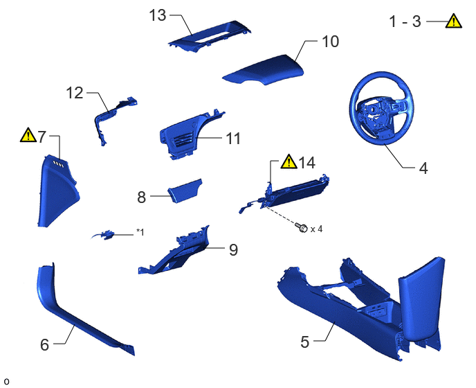
| Procedure | Part Name Code | 
|

|

|
|
|---|---|---|---|---|---|
| 1 | PRECAUTION | - | ( ) |
- | - |
| 2 | CUSTOMIZE POWER TILT AND POWER TELESCOPIC STEERING COLUMN SYSTEM | - | ()
|
- | - |
| 3 | ALIGN FRONT WHEELS FACING STRAIGHT AHEAD | - | ()
|
- | - |
| 4 | STEERING WHEEL ASSEMBLY | 45100 | - | - | - |
| 5 | CONSOLE BOX ASSEMBLY | 58810J | - | - | - |
| 6 | FRONT DOOR SCUFF PLATE LH | 67914B | - | - | - |
| 7 | NO. 1 INSTRUMENT SIDE PANEL | 55317E | ()
|
- | - |
| 8 | INSTRUMENT CLUSTER FINISH PANEL ORNAMENT | 55471A | - | - | - |
| 9 | LOWER INSTRUMENT PANEL FINISH PANEL SUB-ASSEMBLY | 55045 | - | - | - |
| 10 | INSTRUMENT CLUSTER FINISH PANEL ASSEMBLY | 55410C | - | - | - |
| 11 | INSTRUMENT CLUSTER FINISH PANEL SUB-ASSEMBLY | 55404D | - | - | - |
| 12 | INSTRUMENT PANEL FINISH PLATE | 55445B | - | - | - |
| 13 | INSTRUMENT CLUSTER FINISH PANEL END | 55414A | - | - | - |
| 14 | LOWER NO. 1 INSTRUMENT PANEL AIRBAG ASSEMBLY | 73900 | ()
|
- | - |
| *1 | HOOD LOCK CONTROL LEVER SUB-ASSEMBLY | - | - |
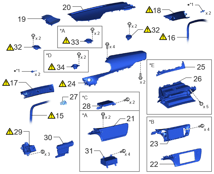
| Procedure | Part Name Code |
|
|
|
|
|---|---|---|---|---|---|
| 15 | FRONT DOOR OPENING TRIM WEATHERSTRIP LH | 62312B | ()
|
- | - |
| 16 | FRONT DOOR OPENING TRIM WEATHERSTRIP RH | 62311B | ()
|
- | - |
| 17 | FRONT PILLAR GARNISH ASSEMBLY LH | 62212B | - | - | - |
| 18 | FRONT PILLAR GARNISH ASSEMBLY RH | 62211U | - | - | - |
| 19 | NO. 2 INSTRUMENT PANEL SPEAKER PANEL | 55473B | - | - | - |
| 20 | NO. 1 INSTRUMENT PANEL SPEAKER PANEL | 55472C | - | - | - |
| 21 | MULTI-DISPLAY ASSEMBLY WITH BRACKET | - | - | - | - |
| 22 | CENTER INSTRUMENT CLUSTER FINISH PANEL SUB-ASSEMBLY | 55405B | - | - | - |
| 23 | RADIO AND DISPLAY RECEIVER ASSEMBLY WITH BRACKET | - | - | - | - |
| 24 | NO. 2 INSTRUMENT PANEL SAFETY PAD SUB-ASSEMBLY | 55403E | ()
|
- | - |
| 25 | LOWER INSTRUMENT CLUSTER FINISH PANEL GARNISH | 55479D | - | - | - |
| 26 | GLOVE COMPARTMENT DOOR ASSEMBLY | 55550 | - | - | - |
| 27 | POWER SWITCH | 89611 | - | - | - |
| 28 | NAVIGATION ECU ASSEMBLY WITH BRACKET | - | - | - | - |
| 29 | SHIFT LOCK CONTROL UNIT ASSEMBLY | 33560 | ()
|
- | - |
| 30 | AIR CONDITIONING CONTROL ASSEMBLY | 55900 | - | - | - |
| 31 | RADIO RECEIVER ASSEMBLY WITH BRACKET | - | - | - | - |
| 32 | FRONT NO. 2 SPEAKER ASSEMBLY | 86160P | ()
|
- | - |
| 33 | FRONT NO. 3 SPEAKER ASSEMBLY | 86160J | ()
|
- | - |
| 34 | NO. 4 SPEAKER WITH BOX ASSEMBLY | 86150D | ()
|
- | - |
| *A | for 14 Speakers | *B | for 6 Speakers |
| *C | w/ Navigation System | *D | w/ Telematics Transceiver |
| *E | for LHD | - | - |
| *1 | FRONT PILLAR GARNISH CLIP | - | - |
| ● | Non-reusable part | - | - |
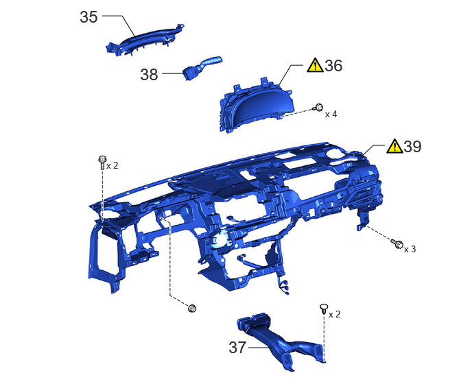
| Procedure | Part Name Code |
|
|
|
|
|---|---|---|---|---|---|
| 35 | LOWER INSTRUMENT COVER SUB-ASSEMBLY | 55407C | - | - | - |
| 36 | COMBINATION METER ASSEMBLY | 83100 | ()
|
- | - |
| 37 | NO. 1 CONSOLE BOX DUCT | 58861B | - | - | - |
| 38 | WINDSHIELD WIPER SWITCH ASSEMBLY | 84650 | - | - | - |
| 39 | INSTRUMENT PANEL SAFETY PAD ASSEMBLY | - | ()
|
- | - |
CAUTION / NOTICE / HINT
The necessary procedures (adjustment, calibration, initialization or registration) that must be performed after parts are removed and installed, or replaced during instrument panel safety pad assembly removal/installation are shown below.
| Replaced Part or Performed Procedure | Necessary Procedure | Effect/Inoperative Function when Necessary Procedure not Performed | Link |
|---|---|---|---|
| Disconnect cable from negative auxiliary battery terminal | Memorize steering angle neutral point | Parking Assist Monitor System | ()
|
| Panoramic View Monitor System | ()
|
- HINT:
- ·
When the cable is disconnected/reconnected to the auxiliary battery terminal, systems temporarily stop operating. However, each system has a function that completes learning the first time the system is used.
-Learning completes when vehicle is driven
Effect/Inoperative Function When Necessary Procedures are not Performed Necessary Procedures Link Lane tracing assist system Drive the vehicle straight ahead at 35 km/h (22 mph) or more for 5 second or more. ( )
Pre-collision system Adaptive high beam system
-Learning completes when vehicle is operated normally
Effect/Inoperative Function When Necessary Procedures are not Performed Necessary Procedures Link Air conditioning system After the ignition switch is turned to ON, the servo motor and expansion valve standard position is recognized. -
·Use the same procedure for RHD and LHD vehicles.
·The procedure listed below is for LHD vehicles.
·All bolts, screws and nuts relevant to installing and removing the instrument panel are shown along with their alphabetical codes in the table.
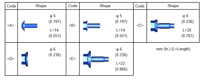 0.24,0.125 0.646,0.396 0.406,0.271 10 false Code 0.25,0.802 0.708,1 0.458,0.198 10 false <A> 0.25,1.969 0.708,2.167 0.458,0.198 10 false <D> 2.417,0.802 2.875,1 0.458,0.198 10 false <B> 4.792,0.802 5.25,1 0.458,0.198 10 false <C> 1.24,0.115 1.74,0.469 0.5,0.354 10 false Shape 1.75,0.469 2.208,0.667 0.458,0.198 10 false φ 5 1.75,0.969 2.208,1.167 0.458,0.198 10 false L=14 2.396,0.115 2.802,0.385 0.406,0.271 10 false Code 3.5,0.115 4,0.469 0.5,0.354 10 false Shape 5.885,0.115 6.385,0.469 0.5,0.354 10 false Shape 4.75,0.125 5.156,0.396 0.406,0.271 10 false Code 2.417,1.969 2.875,2.167 0.458,0.198 10 false <E> 1.708,0.667 2.167,0.865 0.458,0.198 10 false (0.197) 1.708,1.167 2.25,1.448 0.542,0.281 10 false (0.551) 4.083,0.469 4.542,0.667 0.458,0.198 10 false φ 5 4.042,0.667 4.5,0.865 0.458,0.198 10 false (0.197) 4.042,1.167 4.583,1.448 0.542,0.281 10 false (0.551) 4.083,0.969 4.542,1.167 0.458,0.198 10 false L=14 6.417,0.469 6.875,0.667 0.458,0.198 10 false φ 6 6.375,0.667 6.833,0.865 0.458,0.198 10 false (0.236) 6.417,0.969 6.875,1.167 0.458,0.198 10 false L=20 6.375,1.167 6.917,1.448 0.542,0.281 10 false (0.787) 1.75,1.635 2.208,1.833 0.458,0.198 10 false φ 6 1.708,1.833 2.167,2.031 0.458,0.198 10 false (0.236) 4.083,2.135 4.542,2.333 0.458,0.198 10 false L=22 4.083,1.635 4.542,1.833 0.458,0.198 10 false φ 6 4.042,1.833 4.5,2.031 0.458,0.198 10 false (0.236) 4.042,2.333 4.583,2.615 0.542,0.281 10 false (0.866) 5.49,1.625 6.781,1.917 1.292,0.292 10 false mm (in.) (L=Length)
PROCEDURE

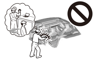
 1. PRECAUTION
|
|
|
2. CUSTOMIZE POWER TILT AND POWER TELESCOPIC STEERING COLUMN SYSTEM
|
|
Click here()
|
3.ALIGN FRONT WHEELS FACING STRAIGHT AHEAD
45100
4.REMOVE STEERING WHEEL ASSEMBLY
58810J
5.REMOVE CONSOLE BOX ASSEMBLY
67914B
6.REMOVE FRONT DOOR SCUFF PLATE LH
Use the same procedure described for the RH side.
Click hereVehicle Interior>INTERIOR PANELS / TRIM>FRONT CONSOLE BOX>REMOVAL
55317E
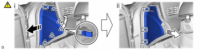
7.REMOVE NO. 1 INSTRUMENT SIDE PANEL

|
Remove in this Direction (1) | 
|
Remove in this Direction (2) |
Using moulding remover B, detach the clip and guide in the removal direction (1) as shown in the illustration.
Detach the guide in the removal direction (2) as shown in the illustration and remove the No. 1 instrument side panel.
55471A
8.REMOVE INSTRUMENT CLUSTER FINISH PANEL ORNAMENT

|
|
Remove in this Direction | - | - |
55045
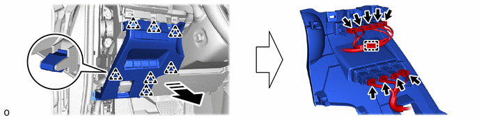
9.REMOVE LOWER INSTRUMENT PANEL FINISH PANEL SUB-ASSEMBLY
- HINT:
-
The illustrations are representative examples, and details may differ.
|
|
Remove in this Direction | - | - |
55410C
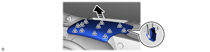
10.REMOVE INSTRUMENT CLUSTER FINISH PANEL ASSEMBLY
|
|
Remove in this Direction | - | - |
55404D
11.REMOVE INSTRUMENT CLUSTER FINISH PANEL SUB-ASSEMBLY
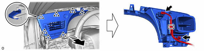
|
|
Remove in this Direction | - | - |
55445B
12.REMOVE INSTRUMENT PANEL FINISH PLATE
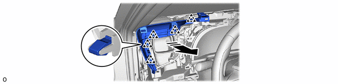
|
|
Remove in this Direction | - | - |
55414A
13.REMOVE INSTRUMENT CLUSTER FINISH PANEL END
- HINT:
-
The illustrations are representative examples, and details may differ.


|
Protective Tape | - | - |
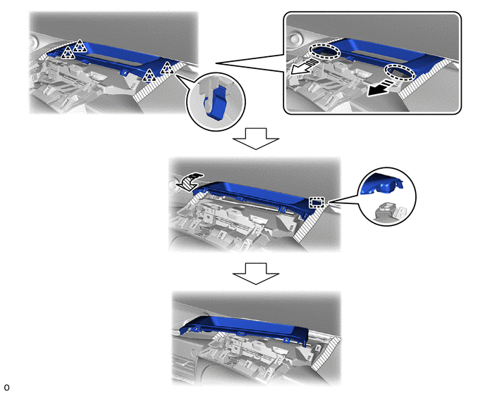

|
Place Hand Here |
|
Remove in this Direction (1) |
|
|
Remove in this Direction (2) | 
|
Remove in this Direction (3) |
73900
14.REMOVE LOWER NO. 1 INSTRUMENT PANEL AIRBAG ASSEMBLY
|
|
Click here()
|
62312B
15.REMOVE FRONT DOOR OPENING TRIM WEATHERSTRIP LH
|
|
|
62311B
16.REMOVE FRONT DOOR OPENING TRIM WEATHERSTRIP RH
|
|
|
62212B
17.REMOVE FRONT PILLAR GARNISH ASSEMBLY LH
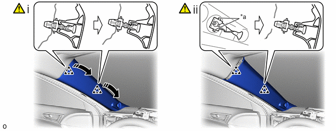
| *a | Release Lever | - | - |
|
|
Remove in this Direction | - | - |
Detach the front pillar garnish assembly LH from the base of the front pillar garnish clip as shown in the illustration.
While pushing the release lever of the front pillar garnish clip as shown in the illustration, detach it.
When the front pillar garnish clip cannot be detached easily:
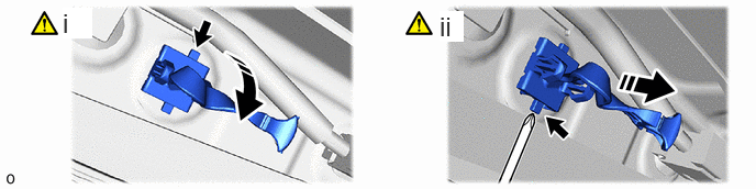
|
|
Pull in this Direction | - | - |
While pushing the tab of the front pillar garnish clip shown in the illustration with your finger, move the front pillar garnish clip in the direction shown in the illustration.
While pulling the front pillar garnish clip as shown in the illustration, push the release lever of the front pillar garnish clip shown in the illustration with a screwdriver and detach the front pillar garnish clip.
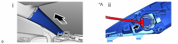
| *A | for 14 Speakers | - | - |
|
|
Remove in this Direction | - | - |
Detach the guide and remove the front pillar garnish assembly LH as shown in the illustration.
for 14 Speakers:
Disconnect the connector and front No. 2 speaker assembly.
Protect the curtain shield airbag assembly LH:

| *a | Protective Cover | - | - |
|
|
Adhesive Tape | - | - |
Cover the curtain shield airbag assembly LH with a protective cover, such as a cloth, and secure the edges of the cover with tape as shown in the illustration.
- NOTICE:
-
Cover the curtain shield airbag assembly LH with a protective cover as soon as the front pillar garnish LH is removed.
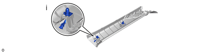
Remove the 2 front pillar garnish clips from the front pillar garnish assembly LH.
62211U
18.REMOVE FRONT PILLAR GARNISH ASSEMBLY RH
Use the same procedure described for the LH side.
55473B
19.REMOVE NO. 2 INSTRUMENT PANEL SPEAKER PANEL
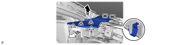
|
|
Remove in this Direction (1) |
|
Remove in this Direction (2) |
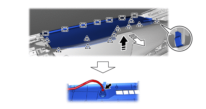
55472C
20.REMOVE NO. 1 INSTRUMENT PANEL SPEAKER PANEL
|
|
Remove in this Direction (1) |
|
Remove in this Direction (2) |
21.REMOVE MULTI-DISPLAY ASSEMBLY WITH BRACKET (for 14 Speakers)
55405B
22.REMOVE CENTER INSTRUMENT CLUSTER FINISH PANEL SUB-ASSEMBLY (for 6 Speakers)
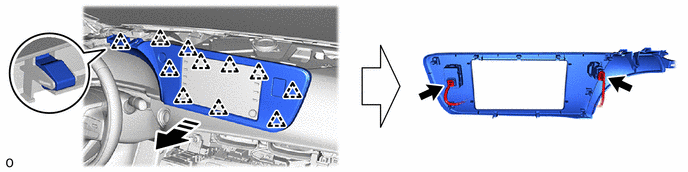
|
|
Remove in this Direction | - | - |
23.REMOVE RADIO AND DISPLAY RECEIVER ASSEMBLY WITH BRACKET (for 6 Speakers)
55403E
24.REMOVE NO. 2 INSTRUMENT PANEL SAFETY PAD SUB-ASSEMBLY
|
|
Click here()
|
55479D
25.REMOVE LOWER INSTRUMENT CLUSTER FINISH PANEL GARNISH (for LHD)
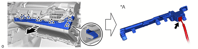
| *A | w/ Interior Illumination | - | - |
|
|
Remove in this Direction | - | - |
55550
26.REMOVE GLOVE COMPARTMENT DOOR ASSEMBLY (for LHD)
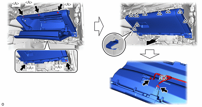
|
|
Remove in this Direction | - | - |
89611
27.REMOVE POWER SWITCH
28.REMOVE NAVIGATION ECU ASSEMBLY WITH BRACKET (w/ Navigation System)
33560
29.REMOVE SHIFT LOCK CONTROL UNIT ASSEMBLY
|
|
Click here()
|
55900
30.REMOVE AIR CONDITIONING CONTROL ASSEMBLY
31.REMOVE RADIO RECEIVER ASSEMBLY WITH BRACKET (for 14 Speakers)
86160P
32.REMOVE FRONT NO. 2 SPEAKER ASSEMBLY
|
|
Click here()
|
86160J
33.REMOVE FRONT NO. 3 SPEAKER ASSEMBLY (for 14 Speakers)
|
|
Click here()
|
86150D
34.REMOVE NO. 4 SPEAKER WITH BOX ASSEMBLY (w/ Telematics Transceiver)
|
|
Click here()
|
55407C
35.REMOVE LOWER INSTRUMENT COVER SUB-ASSEMBLY
83100
36.REMOVE COMBINATION METER ASSEMBLY
|
|
Click here()
|
58861B
37.REMOVE NO. 1 CONSOLE BOX DUCT

84650
38.REMOVE WINDSHIELD WIPER SWITCH ASSEMBLY
39.REMOVE INSTRUMENT PANEL SAFETY PAD ASSEMBLY
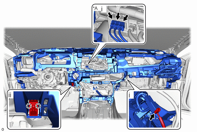
| *A | w/ Telematics Transceiver | - | - |
Disconnect each connector.
Detach the claw and remove the cooler thermistor (room temperature sensor).
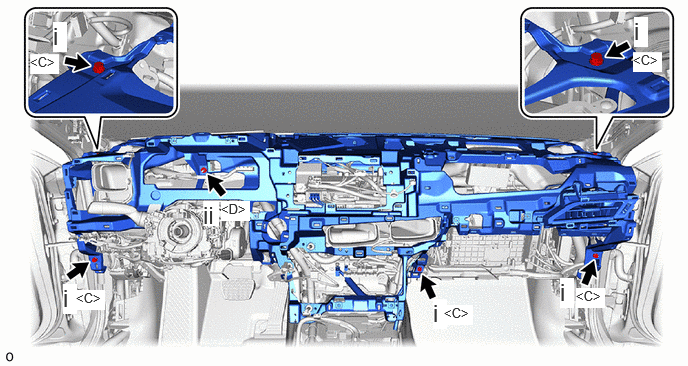
Remove the 5 bolts <C>.
Remove the nut <D>.
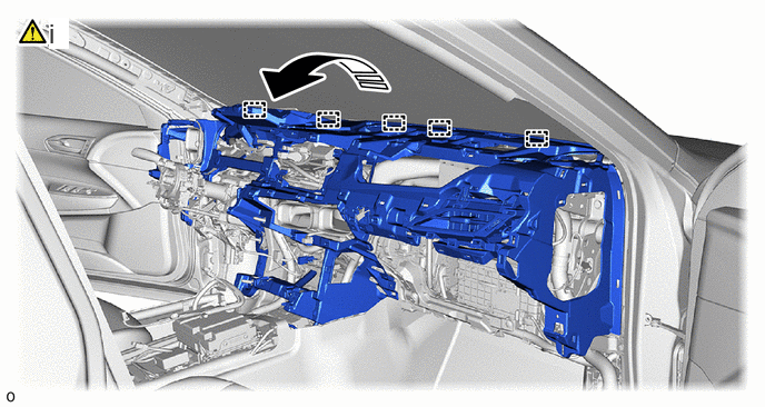
|
|
Remove in this Direction | - | - |
Lift in the direction indicated by the arrow shown in the illustration to detach the guide.
- NOTICE:
- ·
Do not damage the instrument panel safety pad assembly or vehicle interior.
·Make sure that the wire harness does not get caught on anything as it may become damaged.
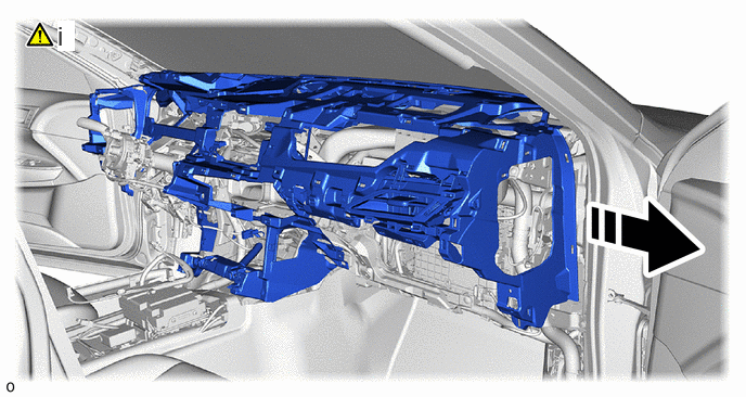
|
|
Remove in this Direction | - | - |
Remove the instrument panel safety pad assembly as shown in the illustration.
- NOTICE:
- ·
Do not damage the instrument panel safety pad assembly or vehicle interior.
·Make sure that the wire harness does not get caught on anything as it may become damaged.