FRONT SUSPENSION FRONT LOWER SUSPENSION ARM INSTALLATION
CAUTION / NOTICE / HINT
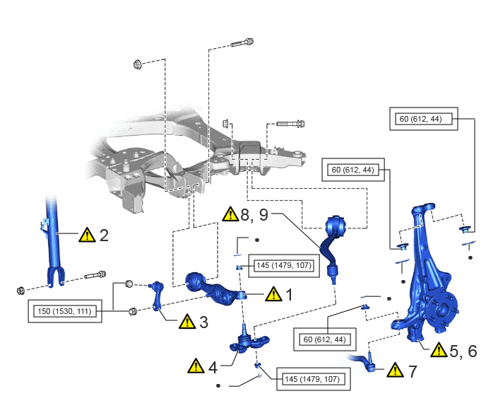
| Procedure | Part Name Code | 
|

|

|
|
|---|---|---|---|---|---|
| 1 | TEMPORARILY TIGHTEN FRONT LOWER SUSPENSION ARM ASSEMBLY LH | 48640 | ( ) |
- | - |
| 2 | TEMPORARILY TIGHTEN FRONT SHOCK ABSORBER ASSEMBLY LH | 48520 | ()
|
- | - |
| 3 | FRONT STABILIZER LINK ASSEMBLY LH | 48810 | ()
|
- | - |
| 4 | FRONT LOWER BALL JOINT ASSEMBLY LH | 43340A | ()
|
- | - |
| 5 | INSTALL STEERING KNUCKLE LH | 43212 | - | - | - |
| 6 | CONNECT STEERING KNUCKLE LH | 43212 | ()
|
- | - |
| 7 | TIE ROD ASSEMBLY LH | 45470 | ()
|
- | - |
| 8 | TEMPORARILY TIGHTEN LOWER NO. 2 SUSPENSION ARM ASSEMBLY LH | 48670A | ()
|
- | - |
| 9 | LOWER NO. 2 SUSPENSION ARM ASSEMBLY LH | 48670A | ()
|
- | - |

|
Tightening torque for "Major areas involving basic vehicle performance such as moving/turning/stopping": N*m (kgf*cm, ft.*lbf) | ● | Non-reusable part |
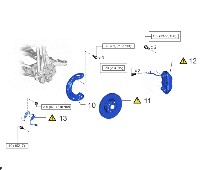
| Procedure | Part Name Code |
|
|
|
|
|---|---|---|---|---|---|
| 10 | FRONT DISC BRAKE DUST COVER LH | 47782 | - | - | - |
| 11 | FRONT DISC LH | 43516 | ()
|
- | - |
| 12 | DISC BRAKE CYLINDER ASSEMBLY LH | 47750 | ()
|
- | - |
| 13 | FRONT SKID CONTROL SENSOR WIRE LH | 89516F | ()
|
- | - |
|
|
Tightening torque for "Major areas involving basic vehicle performance such as moving/turning/stopping": N*m (kgf*cm, ft.*lbf) | 
|
N*m (kgf*cm, ft.*lbf): Specified torque |
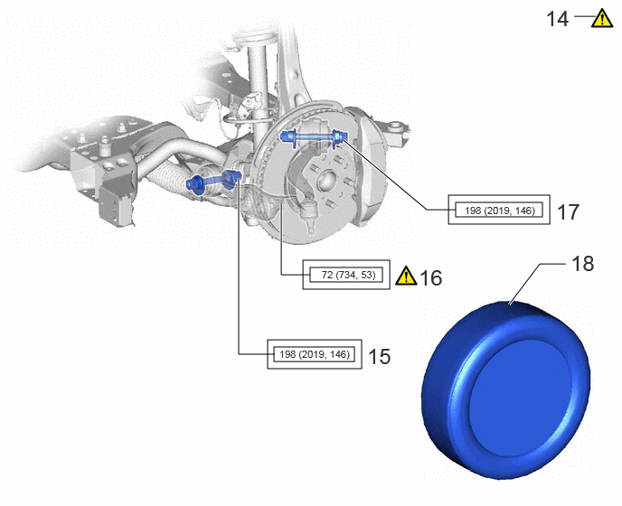
| Procedure | Part Name Code |
|
|
|
|
|---|---|---|---|---|---|
| 14 | STABILIZE SUSPENSION | - | ()
|
- | - |
| 15 | FULLY TIGHTEN FRONT LOWER SUSPENSION ARM ASSEMBLY LH | 48640 | - | - | - |
| 16 | FULLY TIGHTEN FRONT SHOCK ABSORBER ASSEMBLY LH | 48520 | ()
|
- | - |
| 17 | FULLY TIGHTEN LOWER NO. 2 SUSPENSION ARM ASSEMBLY LH | 48670A | - | - | - |
| 18 | FRONT TIRE | - | - | - | - |
|
|
Tightening torque for "Major areas involving basic vehicle performance such as moving/turning/stopping": N*m (kgf*cm, ft.*lbf) | - | - |
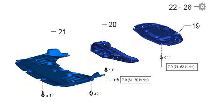
| Procedure | Part Name Code |
|
|
|
|
|---|---|---|---|---|---|
| 19 | FRONT COMPARTMENT UNDER COVER ASSEMBLY | 51420A | - | - | - |
| 20 | FRONT LOWER SUSPENSION MEMBER PROTECTOR | 51219 | - | - | - |
| 21 | FRONT COMPARTMENT UNDER COVER | 51441N | - | - | - |
| 22 | INSTALL CABLE TO NEGATIVE AUXILIARY BATTERY TERMINAL | - | - | - | ()
|
| 23 | INSPECT AND ADJUST FRONT WHEEL ALIGNMENT | - | - | - | - |
| 24 | CHECK FOR SPEED SENSOR SIGNAL | - | - | - | ()
|
| 25 | INITIALIZATION AFTER RECONNECTING BATTERY TERMINAL | - | - | - | ()
|
| 26 | PERFORM INITIALIZATION | - | - | - | ()
|
|
|
N*m (kgf*cm, ft.*lbf): Specified torque | - | - |
| ● | Non-reusable part | ★ | Precoated part |
CAUTION / NOTICE / HINT
- HINT:
- ·
Use the same procedure for the RH and LH side.
·The following procedure is for the LH side.
PROCEDURE

 48640
1.TEMPORARILY TIGHTEN FRONT LOWER SUSPENSION ARM ASSEMBLY LH
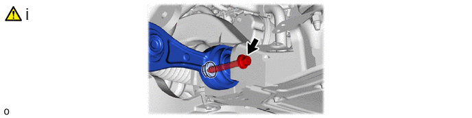
Install the front suspension lower arm assembly LH with the bolt and nut and temporarily tighten the bolt.
- HINT:
-
After stabilizing the suspension, tighten the bolt.
48520
2.TEMPORARILY TIGHTEN FRONT SHOCK ABSORBER ASSEMBLY LH
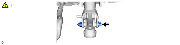
Temporarily tighten the bolt and nut on the lower side of the front shock absorber assembly LH.
- NOTICE:
-
Because the nut has its own stopper, turn the bolt.
48810
3.INSTALL FRONT STABILIZER LINK ASSEMBLY LH
|
|
Click here()
|
43340A
4.INSTALL FRONT LOWER BALL JOINT ASSEMBLY LH
|
|
Click here()
|
43212
5.INSTALL STEERING KNUCKLE LH
43212
6.CONNECT STEERING KNUCKLE LH
|
|
Click here()
|
45470
7.CONNECT TIE ROD ASSEMBLY LH
|
|
Click here()
|
48670A
8.TEMPORARILY TIGHTEN LOWER NO. 2 SUSPENSION ARM ASSEMBLY LH
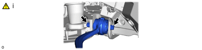
Install the front lower No. 2 suspension arm assembly LH with the bolt and nut and temporarily tighten the bolt.
- HINT:
-
After stabilizing the suspension, tighten the bolt.
48670A
9.CONNECT LOWER NO. 2 SUSPENSION ARM ASSEMBLY LH
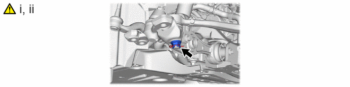
Connect the lower No. 2 suspension arm assembly LH to the front lower ball joint assembly LH with the nut.
- Torque:
- 145 N*m (1479 kgf*cm, 107 ft.*lbf)
- NOTICE:
-
Keep the threads and taper free of oil and grease.
Install a new clip.
- NOTICE:
-
Further tighten the nut up to 60° if the holes for the clip are not aligned.
47782
10.INSTALL FRONT DISC BRAKE DUST COVER LH
43512
11.INSTALL FRONT DISC LH
|
|
Click here()
|
47750
12.CONNECT DISC BRAKE CYLINDER ASSEMBLY LH
|
|
Click here()
|
89516F
13.CONNECT FRONT SKID CONTROL SENSOR WIRE LH
|
|
Click here()
|
14. STABILIZE SUSPENSION
|
|
Click here()
|
48640
15.FULLY TIGHTEN FRONT LOWER SUSPENSION ARM ASSEMBLY LH
- Torque:
- 198 N*m (2019 kgf*cm, 146 ft.*lbf)
48520
16.FULLY TIGHTEN FRONT SHOCK ABSORBER ASSEMBLY LH
Temporarily tighten the bolt on the lower side of the front shock absorber assembly LH.
- Torque:
- 72 N*m (734 kgf*cm, 53 ft.*lbf)
- NOTICE:
-
Because the nut has its own stopper, turn the bolt.
48670A
17.FULLY TIGHTEN LOWER NO. 2 SUSPENSION ARM ASSEMBLY LH
- Torque:
- 198 N*m (2019 kgf*cm, 146 ft.*lbf)
18.INSTALL FRONT TIRE
51420A
19.INSTALL FRONT COMPARTMEMT UNDER COVER ASSEMBLY
51219
20.INSTALL FRONT LOWER SUSPENSION MEMBER PROTECTOR
51441N
21.INSTALL FRONT COMPARTMENT UNDER COVER
22.INSTALL CABLE TO NEGATIVE AUXILIARY BATTERY TERMINAL
23.INSPECT AND ADJUST FRONT WHEEL ALIGNMENT
24.CHECK FOR SPEED SENSOR SIGNAL
25. INITIALIZATION AFTER RECONNECTING BATTERY TERMINAL
Click hereGeneral>SETUP>WHEN DISCONNECTING OR RECONNECTING BATTERY TERMINAL>WORK PROCEDURE
- HINT:
-
When disconnecting and reconnecting the battery, there is an automatic learning function that completes learning when the respective system is used.
-
Click hereGeneral>SETUP>WHEN DISCONNECTING OR RECONNECTING BATTERY TERMINAL>AUTOMATIC LEARNING CHART
26.PERFORM INITIALIZATION