FRONT SUSPENSION FRONT SHOCK ABSORBER INSTALLATION
CAUTION / NOTICE / HINT
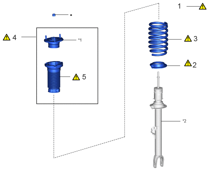
| Procedure | Part Name Code | 
|

|

|
|
|---|---|---|---|---|---|
| 1 | INSTALL SST | - | ( ) |
- | - |
| 2 | FRONT LOWER COIL SPRING INSULATOR LH | 48158C | ()
|
- | - |
| 3 | FRONT COIL SPRING LH | 48132 | ()
|
- | - |
| 4 | FRONT SUSPENSION SUPPORT ASSEMBLY | 48680 | ()
|
- | - |
| 5 | FRONT UPPER COIL SPRING INSULATOR LH | 48157C | ()
|
- | - |
| *1 | FRONT SUSPENSION SUPPORT SUB-ASSEMBLY LH | *2 | FRONT SHOCK ABSORBER ASSEMBLY LH |
| ● | Non-reusable part | - | - |
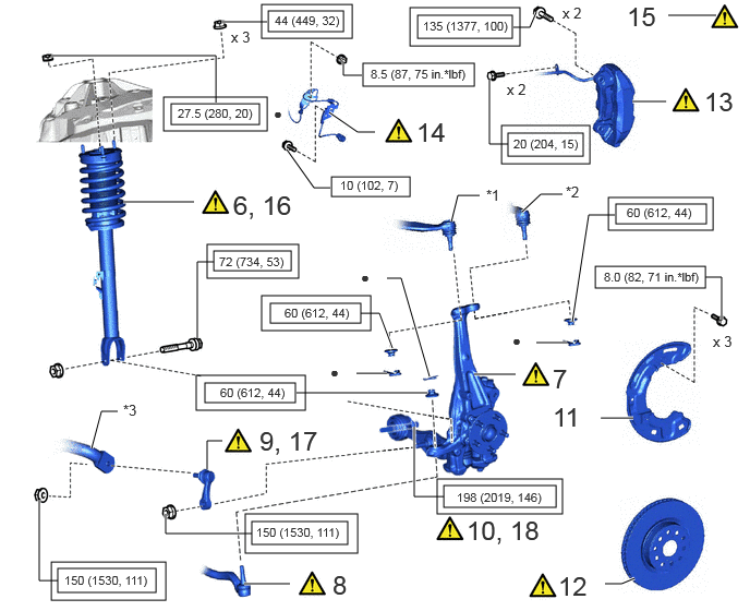
| Procedure | Part Name Code |
|
|
|
|
|---|---|---|---|---|---|
| 6 | TEMPORARILY TIGHTEN FRONT SHOCK ABSORBER WITH COIL SPRING | - | ()
|
- | - |
| 7 | CONNECT STEERING KNUCKLE LH | 43212 | ()
|
- | - |
| 8 | TIE ROD ASSEMBLY LH | 45470 | ()
|
- | - |
| 9 | TEMPORARILY TIGHTEN FRONT STABILIZER LINK ASSEMBLY LH | 48810 | ()
|
- | - |
| 10 | TEMPORARILY TIGHTEN FRONT LOWER SUSPENSION ARM ASSEMBLY LH | 48640 | ()
|
- | - |
| 11 | FRONT DISC BRAKE DUST COVER LH | 47782 | - | - | - |
| 12 | FRONT DISC | 43512 | ()
|
- | - |
| 13 | DISC BRAKE CYLINDER ASSEMBLY LH | 47750 | ()
|
- | - |
| 14 | FRONT SKID CONTROL SENSOR WIRE LH | 89516F | ()
|
- | - |
| 15 | STABILIZE SUSPENSION | - | ()
|
- | - |
| 16 | FULLY TIGHTEN FRONT SHOCK ABSORBER WITH COIL SPRING | - | ()
|
- | - |
| 17 | FULLY TIGHTEN FRONT STABILIZER LINK ASSEMBLY LH | 48810 | ()
|
- | - |
| 18 | FULLY TIGHTEN FRONT LOWER SUSPENSION ARM ASSEMBLY LH | 48640 | ()
|
- | - |
| *1 | FRONT UPPER NO. 1 SUSPENSION ARM ASSEMBLY LH | *2 | FRONT UPPER NO. 2 SUSPENSION ARM ASSEMBLY LH |
| *3 | FRONT STABILIZER BAR | - | - |

|
Tightening torque for "Major areas involving basic vehicle performance such as moving/turning/stopping" : N*m (kgf*cm, ft.*lbf) | 
|
N*m (kgf*cm, ft.*lbf): Specified torque |
| ● | Non-reusable part | - | - |
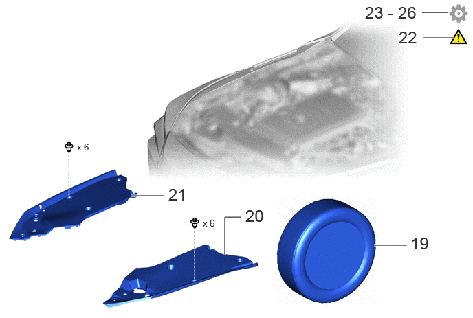
| Procedure | Part Name Code |
|
|
|
|
|---|---|---|---|---|---|
| 19 | FRONT WHEEL | - | - | - | - |
| 20 | UPPER RADIATOR SUPPORT SEAL | 53292A | - | - | - |
| 21 | RADIATOR COVER PLATE | 53291B | - | - | - |
| 22 | CABLE TO NEGATIVE AUXILIARY BATTERY TERMINAL | - | ()
|
- | - |
| 23 | INSPECT AND ADJUST FRONT WHEEL ALIGNMENT | - | - | - | - |
| 24 | CHECK FOR SPEED SENSOR SIGNAL | - | - | - | ()
|
| 25 | INITIALIZATION AFTER RECONNECTING BATTERY TERMINAL | - | - | - | ()
|
| 26 | PERFORM INITIALIZATION | - | - | - | ()
|
CAUTION / NOTICE / HINT
- HINT:
- ·
Use the same procedure for the RH and LH side.
·The following procedure is for the LH side.
PROCEDURE

 1.INSTALL SST
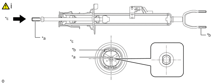
| *a | Cutout | *b | Bottom End Mount |
| *c | Viewpoint A | - | - |
Align the cutout on end of the shock rod of the front shock absorber assembly LH with the installation position.
- NOTICE:
-
Be sure to install the part so that the cutout on the front suspension support sub-assembly LH and the cutout on the shock rod end are aligned.
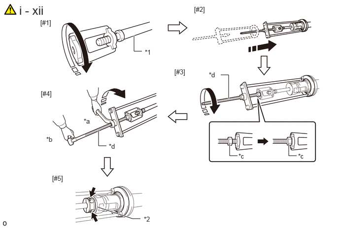
| *1 | Front Shock Absorber Assembly LH | *2 | Shock Absorber Outer Shell |
| *a | Turn | *b | Hold |
| *c | Fixing Nut | *d | Bolt |
Install SST (09727-58100) and SST (09727-58110) to the front shock absorber assembly LH.
- SST
- 09727-58100
09727-58110
09727-58010 (09727-58020)
- NOTICE:
-
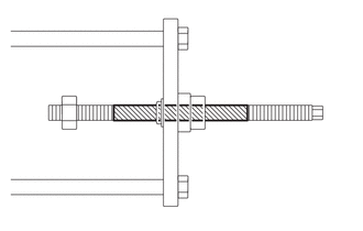 0,0 0,0 false

Application Area
-
Apply molybdenum grease to the bolt (area with diagonal lines) of SST (09727-58010).
Install SST (09727-58020) to the end of the shock rod of the front shock absorber assembly LH.[#1]
Install SST (09727-58010) to the front shock absorber assembly LH.[#2]
- NOTICE:
-
Take due care when installing SST (09727-58010) to ensure the shock rod is not damaged.
Secure the SST (09727-58010) bolt and SST (09727-58020) with the fixing nut.[#3]
After securing the SST (09727-58010) bolt, rotate the nut clockwise.[#4]
- HINT:
-
Extend the shock rod to its maximum length to install SST (09727-58100) and SST (09727-58120).
Using a piece of cloth, etc., clean the shock rod and remove any foreign matter and oil.
- NOTICE:
-
Thoroughly clean the shock rod to prevent damage to the shock rod due to contact of foreign matter.
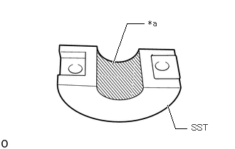
| *a | Installation Surface |
Clean the surface of SST (09727-58110) to which the front shock absorber assembly LH is installed and remove any foreign matter and oil.
- NOTICE:
-
Thoroughly clean the installation surface to prevent damage to the shock rod due to contact of foreign matter.
Using a long ball hexagon 5, install SST (09727-58100) and SST (09727-58110) to the shock rod.[#5]
- NOTICE:
-
Before installing, check the position of the cutout on end of the shock rod.
- HINT:
-
Install SST (09727-58100) and SST (09727-58110) to the base of the shock rod and check that SST (09727-58100) and SST (09727-58110) are securing the shock rod.
After securing the SST (09727-58010) bolt, rotate the nut counterclockwise.
Check that the shock rod and SST (09727-58020) have become free before releasing the fixing nut and removing SST (09727-58010) from the shock rod.
- NOTICE:
-
Take due care when removing SST (09727-58010) to ensure the shock rod is not damaged.
Remove SST (09727-58020) from the end of the shock rod.
Using a piece of cloth, etc., clean the end of the shock rod threads and remove any foreign matter and oil.
48158C
2.INSTALL FRONT LOWER COIL SPRING INSULATOR LH
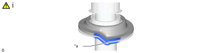
| *a | Depression | - | - |
Install the front lower coil spring insulator to the front shock absorber assembly LH.
- NOTICE:
-
When installing the front lower coil spring insulator, fit the insulator to the depression of the spring seat.
48132
3.INSTALL FRONT COIL SPRING LH
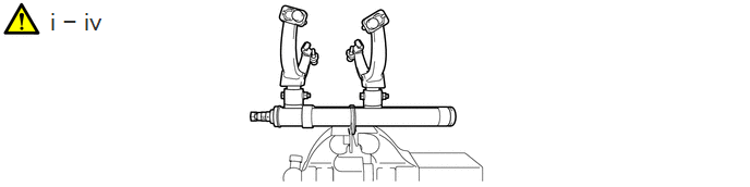
Secure SST in a vise.
- SST
- 09727-30022 (09727-00010, 09727-00022, 09727-00031)
Attach the hooks of each SST arm across the diameter of the coil spring.
- CAUTION:
- ·
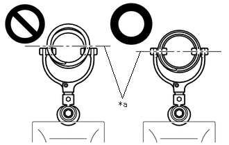 1.563,0.698 1.833,1.479 1.833,1.479 2.104,0.771 false 1.781,1.5 2.094,1.698 0.313,0.198 10 false *a
*a Front Coil Spring Diameter
Do not perform the work without checking to make sure that the claws of the hooks are securely engaged.
·It could cause the hook to slip off and the spring to fly out, which could result in an injury.
·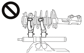
Do not install SST to the front coil spring unless its top and bottom hook distance is set to the widest condition.
·It could cause the hook to slip off and the spring to fly out, which could result in an injury.
·Do not install SST when the distances between the SST arms or the number of coils of the coil spring between the hooks are not the same.
·It could cause the hook to slip off and the spring to fly out, which could result in an injury.
Install the stopper pin to the hook of SST.
- CAUTION:
-
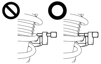
- ·
Check that the stopper pin is securely installed.
·It could cause the hook to slip off and the front coil spring LH to fly out, which could result in an injury.
Using SST, compress the coil spring.
- SST
- 09727-00110
- CAUTION:
- ·
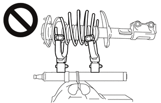
While compressing the spring, if the front coil spring starts to bend into a bow shape, do not continue the work.
·It could cause the hook to slip off and the spring to fly out, which could result in an injury.
·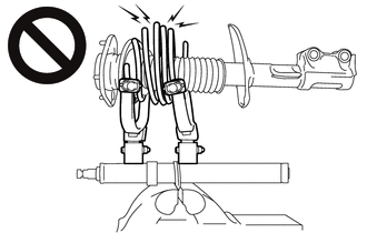
While compressing the spring, if the front coil spring starts to bend into a bow shape, do not continue the work.
·It could cause the hook to slip off and the spring to fly out, which could result in an injury.
·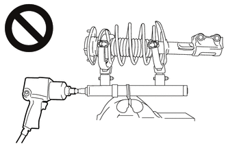
Do not use an impact wrench.
·The threads may be stripped, or the sudden compression may result in slack that causes the hooks to slip off, causing the spring to fly out and possibly resulting in injury.
·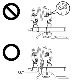 1.042,3.063 1.698,3.063 true 0.75,3 1.063,3.156 0.313,0.156 10 false SST
If a stopper pin touches the coil spring while using SST, remove the stopper pin and continue with the procedure.
If a stopper pin is removed, install SST as shown in the illustration.
·If a hook disengages from the coil spring, the coil spring may fly out, resulting in injury.
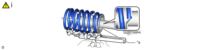
| *a | Depression | - | - |
Install the front coil spring to the front shock absorber assembly LH.
- NOTICE:
-
Make sure that the end of the front coil spring is positioned in the depression of the front lower spring seat.
48680
4.INSTALL FRONT SUSPENSION SUPPORT ASSEMBLY
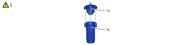
| *a | Front Suspension Support Sub-assembly LH Identification Mark | *b | Front Coil Spring Upper Insulator LH Top Protrusion |
Install the front suspension support sub-assembly LH to the front coil spring upper insulator LH.
- NOTICE:
-
Install the front suspension support sub-assembly LH so that the identification mark on it and the protrusion at the top the front coil spring upper insulator LH come to the positions as shown in the illustration.
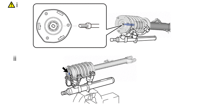
Install the front suspension support assembly to the front shock absorber assembly LH.
- NOTICE:
-
Match the shape of the front shock absorber assembly support ring end to the shape of the front suspension support assembly.
Temporarily tighten a new lock nut.
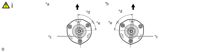
| *a | for LH Side | *b | for RH Side |
| *c | Identification Mark | *d | 61°+/- 2° |
| *e | 29° | - | - |

|
Front of the Vehicle | - | - |
Adjust the front suspension support assembly so that the bolts come to the positions as shown in the illustration, and remove SST from the front coil spring.
- NOTICE:
- ·
Do not use an impact wrench. It will damage SST.
·Make sure that the width across flat on the front shock absorber piston rod end is located parallel to the front shock absorber bushing.
·Make sure of the direction of the front suspension support assembly when removing SST.
48157C
5.INSTALL FRONT UPPER COIL SPRING INSULATOR LH
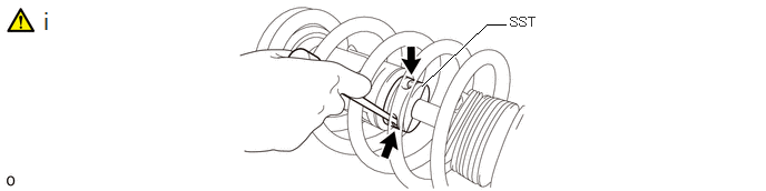
Using a long ball hexagon 5, remove SST (09727-58100) and SST (09727-58110) from the shock rod.
- NOTICE:
- ·
Thoroughly remove SST (09727-58100) and SST (09727-58110).
·When removing SST (09727-58100) and SST (09727-58110), do not fold back the No. 1 front shock absorber dust cover LH in an improper direction and deform it.
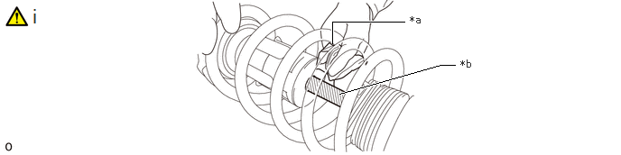
| *a | Cloth, etc. | *b | Shock Rod |
Using a piece of cloth, etc., clean the shock rod and remove any foreign matter and oil.
- NOTICE:
-
Thoroughly clean the shock rod to prevent damage to the shock rod due to contact of foreign matter.
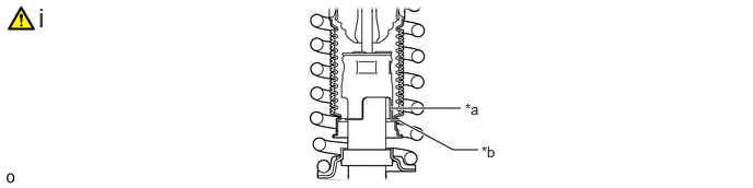
| *a | Front Shock Absorber Assembly LH Claw | *b | End of Front Upper Coil Spring Insulator |
Engage the end of the front upper coil spring insulator to the front shock absorber assembly LH claws.
- NOTICE:
- ·
Make sure that the end of the front upper coil spring insulator is engaged securely to the 4 front shock absorber assembly LH claws.
·Be careful not to deform the bellows of the front upper coil spring insulator.
·Keep the front upper coil spring insulator free of oil and grease.
6.TEMPORARILY TIGHTEN FRONT SHOCK ABSORBER WITH COIL SPRING
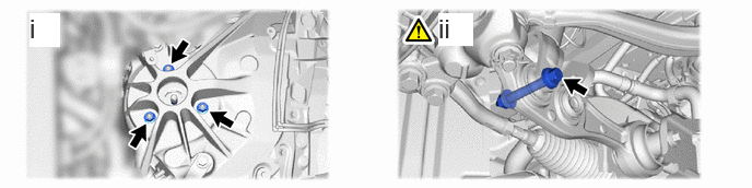
Temporarily tighten the front shock absorber with coil spring (upper side) with the 3 nuts.
- Torque:
- 44 N*m (449 kgf*cm, 32 ft.*lbf)
Temporarily tighten the front shock absorber with coil spring (lower side) to the front lower suspension arm assembly with the bolt and nut.
- NOTICE:
- ·
Insert the bolt from the rear of the vehicle.
·Because the nut has its own stopper, do not turn the nut. Tighten the bolt with the nut secured.
- HINT:
-
Fully tighten the bolt after stabilizing the suspension.
43212
7.CONNECT STEERING KNUCKLE LH
|
|
Click here()
|
45470
8.CONNECT TIE ROD ASSEMBLY LH
|
|
Click here()
|
48810
9.TEMPORARILY TIGHTEN FRONT STABILIZER LINK ASSEMBLY LH
|
|
Click here()
|
48640
10.TEMPORARILY TIGHTEN FRONT LOWER SUSPENSION ARM ASSEMBLY LH
|
|
Click here()
|
47782
11.INSTALL FRONT DISC BRAKE DUST COVER LH
|
|
Click here()
|
43512
12.INSTALL FRONT DISC
|
|
Click here()
|
47750
13.INSTALL DISC BRAKE CYLINDER ASSEMBLY LH
|
|
Click here()
|
89516F
14.CONNECT FRONT SKID CONTROL SENSOR WIRE LH
|
|
Click here()
|
15.STABILIZE SUSPENSION
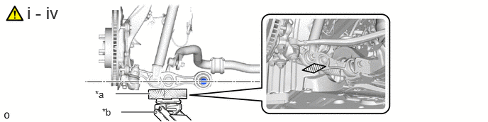
| *a | Wooden Block | *b | Jack |
|
|
Jack Hold Position | - | - |
Install the front wheel.
Lower the vehicle and bounce it up and down several times to stabilize the front suspension.
Remove the front wheel.
Jack up the front lower suspension arm assembly, and place a wooden block under it to avoid damage. Apply load to the suspension so that the front lower suspension arm assembly is placed in a horizontal position.
- CAUTION:
-
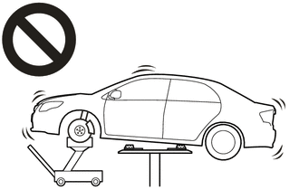
- ·
Do not raise the jack up too high.
·The vehicle could fall, resulting in a serious accident.
- NOTICE:
- ·
When jacking up the front lower suspension arm assembly, be sure to jack it up slowly.
·Make sure to perform this operation with the vehicle kept as low as possible.
16.FULLY TIGHTEN FRONT SHOCK ABSORBER WITH COIL SPRING
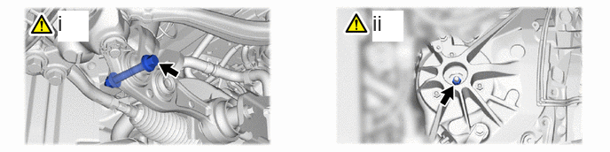
Fully tighten the front shock absorber with coil spring bolt.
- Torque:
- 72 N*m (734 kgf*cm, 53 ft.*lbf)
- NOTICE:
-
Because the nut has its own stopper, do not turn the nut. Tighten the bolt with the nut secured.
Fully tighten the lock nut.
- Torque:
- 27.5 N*m (280 kgf*cm, 20 ft.*lbf)
- NOTICE:
-
Perform this step only when the front shock absorber with coil spring has been disassembled.
48810
17.FULLY TIGHTEN FRONT STABILIZER LINK ASSEMBLY LH
|
|
Click here()
|
48640
18.FULLY TIGHTEN FRONT LOWER SUSPENSION ARM ASSEMBLY LH
|
|
Click here()
|
19.INSTALL FRONT WHEEL
53292A
20.INSTALL UPPER RADIATOR SUPPORT SEAL
53291B
21.INSTALL RADIATOR COVER PLATE
22.CONNECT CABLE TO NEGATIVE AUXILIARY BATTERY TERMINAL
|
|
Click here()
|
23.INSPECT AND ADJUST FRONT WHEEL ALIGNMENT
24.CHECK FOR SPEED SENSOR SIGNAL
25. INITIALIZATION AFTER RECONNECTING BATTERY TERMINAL
Click hereGeneral>SETUP>WHEN DISCONNECTING OR RECONNECTING BATTERY TERMINAL>WORK PROCEDURE
- HINT:
-
When disconnecting and reconnecting the battery, there is an automatic learning function that completes learning when the respective system is used.
-
Click hereGeneral>SETUP>WHEN DISCONNECTING OR RECONNECTING BATTERY TERMINAL>AUTOMATIC LEARNING CHART
26.PERFORM INITIALIZATION