PARKING BRAKE ELECTRIC PARKING BRAKE SYSTEM C11332A Unified Electric Parking Brake Actuator Performance Signal Stuck In Range C13B813 Electric Parking Brake Actuator Circuit Open C13B877 Electric Parking Brake Actuator Commanded Position Not Reachable C13B879 Electric Parking Brake Actuator Mechanical Linkage Failure
DESCRIPTION
| DTC No. | Detection Item | DTC Detection Condition | Trouble Area | Memory | DTC Output from | Priority | Note |
|---|---|---|---|---|---|---|---|
| C11332A | Unified Electric Parking Brake Actuator Performance Signal Stuck In Range | ·
Diagnosis Condition: Electric parking brake operating ·
Malfunction Status: Motor lock, gear lock, stuck cable ·
Detection Time: - |
·
Parking brake actuator assembly with bracket ·
Parking brake cable (Parking brake actuator assembly with bracket) ·
Parking brake assembly ·
Wire harness or connector ·
No. 2 skid control ECU (brake actuator assembly) |
DTC stored | Brake/EPB | B | An electric parking brake system malfunction is displayed on the multi-information display. |
| C13B813 | Electric Parking Brake Actuator Circuit Open | ·
Diagnosis Condition: Electric parking brake operating ·
Malfunction Status: Cable cut ·
Detection Time: - |
·
Parking brake actuator assembly with bracket ·
Parking brake cable (Parking brake actuator assembly with bracket) ·
Parking brake assembly ·
Wire harness or connector ·
No. 2 skid control ECU (brake actuator assembly) |
DTC stored | Brake/EPB | B | An electric parking brake system malfunction is displayed on the multi-information display. |
| C13B877 | Electric Parking Brake Actuator Commanded Position Not Reachable | ·
Diagnosis Condition: Electric parking brake operating ·
Malfunction Status: When defective operation of the motor, gear or cable is detected ·
Detection Time: - |
·
Parking brake actuator assembly with bracket ·
Parking brake cable (Parking brake actuator assembly with bracket) ·
Parking brake assembly ·
Wire harness or connector ·
No. 2 skid control ECU (brake actuator assembly) |
DTC stored | Brake/EPB | B | An electric parking brake system malfunction is displayed on the multi-information display. |
| C13B879 | Electric Parking Brake Actuator Mechanical Linkage Failure | ·
Diagnosis Condition: Electric parking brake operating ·
Malfunction Status: When a disengaged gear, free spinning gear or disconnected cable is detected ·
Detection Time: - |
·
Parking brake actuator assembly with bracket ·
Parking brake cable (Parking brake actuator assembly with bracket) ·
Parking brake assembly ·
Wire harness or connector ·
No. 2 skid control ECU (brake actuator assembly) |
DTC stored | Brake/EPB | B | An electric parking brake system malfunction is displayed on the multi-information display. |
| Vehicle Condition | ||||
|---|---|---|---|---|
| Pattern 1 | Pattern 2 | Pattern 3 | ||
| Diagnosis Condition | Electric parking brake operating | ○ | ○ | ○ |
| Malfunction Status | Motor lock | ○ | - | - |
| Gear lock | - | ○ | - | |
| Stuck cable | - | - | ○ | |
| Detection Time | - | - | - | |
| Number of Trips | 1 trip | 1 trip | 1 trip | |
- HINT:
-
DTC will be output when conditions for either of the patterns in the table above are met.
| Vehicle Condition | ||||
|---|---|---|---|---|
| Pattern 1 | Pattern 2 | Pattern 3 | ||
| Diagnosis Condition | Electric parking brake operating | ○ | ○ | ○ |
| Malfunction Status | Defective motor operation is detected | ○ | - | - |
| Defective gear operation is detected | - | ○ | - | |
| Defective cable operation is detected | - | - | ○ | |
| Detection Time | - | - | - | |
| Number of Trips | 1 trip | 1 trip | 1 trip | |
- HINT:
-
DTC will be output when conditions for either of the patterns in the table above are met.
| Vehicle Condition | ||||
|---|---|---|---|---|
| Pattern 1 | Pattern 2 | Pattern 3 | ||
| Diagnosis Condition | Electric parking brake operating | ○ | ○ | ○ |
| Malfunction Status | Disengaged gear is detected | ○ | - | - |
| Free spinning gear is detected | - | ○ | - | |
| Disconnected cable is detected | - | - | ○ | |
| Detection Time | - | - | - | |
| Number of Trips | 1 trip | 1 trip | 1 trip | |
- HINT:
-
DTC will be output when conditions for either of the patterns in the table above are met.
WIRING DIAGRAM
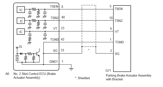
CAUTION / NOTICE / HINT
- NOTICE:
- ·
Although DTCs C11332A, C13B813, C13B877 or C13B879 may be stored after forcibly releasing the parking brake, this is not a malfunction.
·To ensure that the electric parking brake does not operate, wait for 3 minutes or more with the ignition switch off, the driver door closed, and the brake pedal not depressed, then disconnect each connector, fuse and relay.
·After replacing the No. 2 skid control ECU (brake actuator assembly), perform "Calibration".
Click hereBrake>BRAKE CONTROL / DYNAMIC CONTROL SYSTEMS>ELECTRONICALLY CONTROLLED BRAKE SYSTEM>UTILITY
·After replacing the No. 2 skid control ECU (brake actuator assembly), perform "EPB Initialize" and "Acquire Tension Sensor Zero Point".
Click hereBrake>PARKING BRAKE>ELECTRIC PARKING BRAKE SYSTEM>UTILITY
·After replacing the parking brake actuator assembly with bracket, perform "EPB Initialize" and "Acquire Tension Sensor Zero Point".
Click hereBrake>PARKING BRAKE>ELECTRIC PARKING BRAKE SYSTEM>UTILITY
PROCEDURE
Check if DTCs other than C11332A, C13B813, C13B877 or C13B879 are output.
- Chassis > Brake/EPB > Trouble Codes
- 50001 435
- Result:
Result Proceed to Only C11332A, C13B813, C13B877 or C13B879 is output A C11332A, C13B813, C13B877 or C13B879 and other DTCs are output B
A
B
Check that the parking brake cable is not cracked or stuck, and that it is correctly installed.
- HINT:
-
Click hereBrake>PARKING BRAKE>PARKING BRAKE ASSEMBLY>DISASSEMBLY
-
Click hereBrake>PARKING BRAKE>ELECTRIC PARKING BRAKE ACTUATOR>ON-VEHICLE INSPECTION
- OK:
The part has no cracks, is not stuck and is correctly installed.
- Result:
Proceed to OK NG
OK
NG
Replace Parking Brake Actuator Assembly with Bracket:
Click hereBrake>PARKING BRAKE>ELECTRIC PARKING BRAKE ACTUATOR>REMOVAL
Install Parking Brake Cable:
Click hereBrake>PARKING BRAKE>PARKING BRAKE ASSEMBLY>REASSEMBLY
Check if each part is installed properly.
- HINT:
-
Click hereBrake>PARKING BRAKE>PARKING BRAKE ASSEMBLY>DISASSEMBLY
- OK:
The part is installed correctly
- Result:
Proceed to OK NG
OK
NG
Pre-procedure1
Turn the ignition switch off.
Disconnect the A6 No. 2 skid control ECU (brake actuator assembly) connector.
Disconnect the G71 parking brake actuator assembly with bracket connector.
Procedure1
Measure the resistance according to the value(s) in the table below.
- Standard Resistance:
Tester Connection Condition Specified Condition Click Location & Routing(A6,G71)Location & Routingewd_type=routing;type=c,c;code=A6,G71
Click Connector(G71)Body>Floor Wire / No. 3 Floor Wire>Parking Brake Actuator with Bracket Assemblyewd_type=component;type=c;code=G71;pinno=5,10,6,1,2
A6-8 (TSEN) - G71-5 (TSEN) Always Below 1 Ω A6-8 (TSEN) or G71-5 (TSEN) - Body ground Always 10 kΩ or higher A6-40 (TSN2) - G71-10 (TSN2) Always Below 1 Ω A6-40 (TSN2) or G71-10 (TSN2) - Body ground Always 10 kΩ or higher A6-23 (VT) - G71-6 (VT) Always Below 1 Ω A6-23 (VT) or G71-6 (VT) - Body ground Always 10 kΩ or higher A6-42 (TGND) - G71-1 (TGND) Always Below 1 Ω A6-42 (TGND) or G71-1 (TGND) - Body ground Always 10 kΩ or higher A6-33 (SG) - G71-2 (SG) Always Below 1 Ω A6-33 (SG) or G71-2 (SG) - Body ground Always 10 kΩ or higher
- Result:
Proceed to OK NG
Post-procedure1
None
OK
NG
Pre-procedure1
Turn the ignition switch off.
Check that the connector A6 of the No. 2 skid control ECU (brake actuator assembly) is securely installed.
Check that the connector G71 of the parking brake actuator assembly with bracket is securely installed.
Turn the ignition switch to ON.
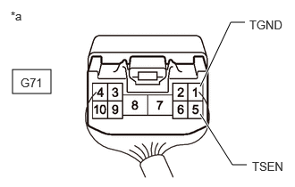
| *a | Component with harness connected
(Parking Brake Actuator Assembly with Bracket) |
Measure the voltage and write down the value.
- Standard Voltage:
Tester Connection Condition Specified Condition Click Location & Routing(G71)Location & Routingewd_type=routing;type=c;code=G71
Click Connector(G71)Body>Floor Wire / No. 3 Floor Wire>Parking Brake Actuator with Bracket Assemblyewd_type=component;type=c;code=G71;pinno=5,1
G71-5 (TSEN) - G71-1 (TGND) Ignition switch ON 0.35 to 4.5 V
Procedure1
Check the values by referring to the table below.
- HINT:
-
This procedure is performed to compare the difference between the actual voltage and the voltage recognized by the ECU.
- Chassis > Brake/EPB > Data List
-
Tester Display Measurement Item Range Normal Condition Diagnostic Note Tension 1 Voltage Tension sensor 1 value input information is displayed Min.: 0.00 V
Max.: 5.00 V0.35 to 4.50 V When not normal, tension sensor signal system may be malfunctioning Invalid Tension Sensor Comp Tension sensor comparison invalid details are displayed Enable / Disable Enable -
- Chassis > Brake/EPB > Data List
-
Tester Display Tension 1 Voltage Invalid Tension Sensor Comp - 50003 435 322,341
- OK:
Difference between the voltage values of the Data List and actual measurement check item is within +/-0.2 V and enabled
- Result:
Proceed to OK NG
Post-procedure1
None
OK
NG
for LHD: Click hereBrake>BRAKE CONTROL / DYNAMIC CONTROL SYSTEMS>BRAKE ACTUATOR (for LHD)>REMOVAL
for RHD: Click hereBrake>BRAKE CONTROL / DYNAMIC CONTROL SYSTEMS>BRAKE ACTUATOR (for RHD)>REMOVAL
Pre-procedure1
Turn the ignition switch off.
Check that the connector A6 of the No. 2 skid control ECU (brake actuator assembly) is securely installed.
Check that the connector G71 of the parking brake actuator assembly with bracket is securely installed.
Turn the ignition switch to ON.
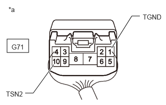
| *a | Component with harness connected
(Parking Brake Actuator Assembly with Bracket) |
Measure the voltage and write down the value.
- Standard Voltage:
Tester Connection Condition Specified Condition Click Location & Routing(G71)Location & Routingewd_type=routing;type=c;code=G71
Click Connector(G71)Body>Floor Wire / No. 3 Floor Wire>Parking Brake Actuator with Bracket Assemblyewd_type=component;type=c;code=G71;pinno=10,1
G71-10 (TSN2) - G71-1 (TGND) Ignition switch ON 0.35 to 4.5 V
Procedure1
Check the values by referring to the table below.
- HINT:
-
This procedure is performed to compare the difference between the actual voltage and the voltage recognized by the ECU.
- Chassis > Brake/EPB > Data List
-
Tester Display Measurement Item Range Normal Condition Diagnostic Note Tension 2 Voltage Tension sensor 2 value input information is displayed Min.: 0.00 V
Max.: 5.00 V0.35 to 4.50 V When not normal, tension sensor signal system may be malfunctioning Invalid Tension Sensor Comp Tension sensor comparison invalid details are displayed Enable / Disable Enable -
- Chassis > Brake/EPB > Data List
-
Tester Display Tension 2 Voltage Invalid Tension Sensor Comp - 50003 435 323,341
- OK:
Difference between the voltage values of the Data List and actual measurement check item is within +/-0.2 V and enabled
- Result:
Proceed to OK NG
Post-procedure1
None
OK
NG
for LHD: Click hereBrake>BRAKE CONTROL / DYNAMIC CONTROL SYSTEMS>BRAKE ACTUATOR (for LHD)>REMOVAL
for RHD: Click hereBrake>BRAKE CONTROL / DYNAMIC CONTROL SYSTEMS>BRAKE ACTUATOR (for RHD)>REMOVAL
Pre-procedure1
None
Procedure1
Clear the DTCs.
- Chassis > Brake/EPB > Clear DTCs
- 50002 435
- Result:
Proceed to NEXT
Post-procedure1
Turn the ignition switch off.
NEXT
Check the output DTC.
- Chassis > Brake/EPB > Trouble Codes
- 50001 435
- Result:
Result Proceed to C11332A, C13B813, C13B877 or C13B879 is output A C11332A, C13B813, C13B877 and C13B879 are not output B
A
B
Perform the lock or release operation with the electric parking brake switch assembly.
- OK:
Electric parking brake operates normally.
- Result:
Proceed to OK NG
OK
Click hereGeneral>INTRODUCTION>HOW TO TROUBLESHOOT ECU CONTROLLED SYSTEMS>HOW TO PROCEED WITH TROUBLESHOOTING
NG
for LHD: Click hereBrake>BRAKE CONTROL / DYNAMIC CONTROL SYSTEMS>BRAKE ACTUATOR (for LHD)>REMOVAL
for RHD: Click hereBrake>BRAKE CONTROL / DYNAMIC CONTROL SYSTEMS>BRAKE ACTUATOR (for RHD)>REMOVAL