HYBRID / BATTERY CONTROL HYBRID CONTROL SYSTEM P1E1500 FC Positive Contactor Actuator Stuck Closed
DTC SUMMARY
MALFUNCTION DESCRIPTION
The EV control ECU detects an ON malfunction due to a high voltage relay (FRB) welded on or stuck on malfunction on the FC converter assembly side.
The cause of this malfunction may be one of the following:
Voltage sensor (FVH) malfunction
FCDC converter control ECU malfunction
Communication (wire harness) malfunction
FC stack assembly (FRB) malfunction
No. 1 EV battery junction block assembly malfunction
FC converter power module transistor malfunction
EV control ECU malfunction
No. 1 EV battery junction block assembly malfunction
Low voltage wire harness malfunction
Low voltage connector malfunction
DESCRIPTION
The FC stack main relay is the relay that connects or disconnects the high voltage power source in accordance with commands from the EV control ECU.
For high voltage wiring diagrams, refer to the system description.
Click hereEngine / Hybrid System>HYBRID / BATTERY CONTROL>HYBRID CONTROL SYSTEM>SYSTEM DESCRIPTION
| DTC No. | Detection Item | DTC Detection Condition | Trouble Area | Warning Indicate | DTC Output from | Priority |
|---|---|---|---|---|---|---|
| P1E1500 | FC Positive Contactor Actuator Stuck Closed | The FC converter assembly output voltage decreases even though the positive side of the high voltage relay of the FC converter assembly is shut off.
(1 trip detection logic) |
·
FC stack main relay (FRB) ·
No. 1 FC converter wire ·
No. 2 FC converter wire ·
FCDC converter control ECU board sub-assembly ·
FC converter power module transistor ·
EV control ECU ·
Wire harness or connector |
Master Warning:
Comes on |
EV | A |
| DTC No. | Data List |
|---|---|
| P1E1500 | ·
FCDC Output Voltage ·
VH-Voltage after Boosting |
CONFIRMATION DRIVING PATTERN
- HINT:
-
After repairs have been completed, clear the DTCs and then check that the vehicle has returned to normal by performing the following All Readiness check procedure.
-
Click hereEngine / Hybrid System>HYBRID / BATTERY CONTROL>HYBRID CONTROL SYSTEM>UTILITY
Turn the ignition switch off and wait for 10 minutes or more.
Turn the ignition switch to ON (READY) and wait for 30 seconds or more.
Turn the ignition switch off and wait for 10 minutes or more.
Enter the following menus: Powertrain / EV / Utility / All Readiness.
Check the DTC judgment result.
- HINT:
- ·
If the judgment result shows NORMAL, the system is normal.
·If the judgment result shows ABNORMAL, the system has a malfunction.
·If the judgment result shows INCOMPLETE, perform driving pattern again.
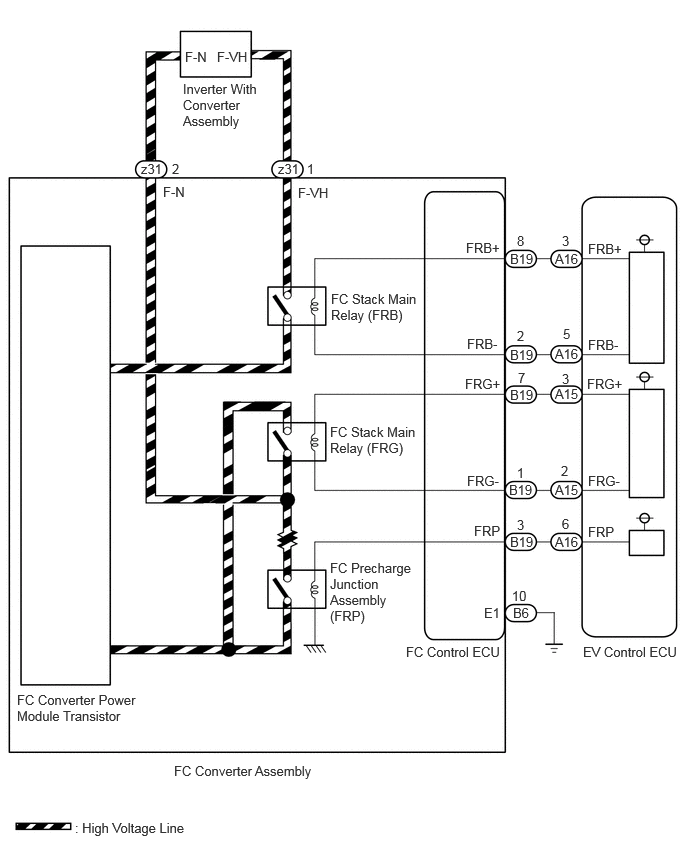
WIRING DIAGRAM
Refer to the wiring diagram for the EV Battery High-Voltage Line Circuit.
CAUTION / NOTICE / HINT
- CAUTION:
- ·
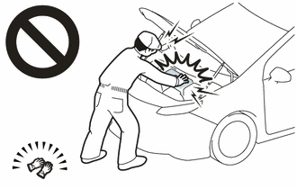
Before the following operations are conducted, take precautions to prevent electric shock by turning the ignition switch off, wearing insulated gloves, and removing the EV battery service plug grip and FC converter power outlet cable on FC converter side.
Make sure to remove the service plug grip first.
-Inspecting the high-voltage system
-Disconnecting the low voltage connector of the inverter with converter assembly
-Disconnecting the low voltage connector of the EV supply battery assembly
-Disconnecting the low voltage connector of the FC converter assembly
·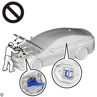
To prevent electric shock, make sure to remove the EV battery service plug grip and FC converter power outlet cable on FC converter side to cut off the high voltage circuit before servicing the vehicle.
·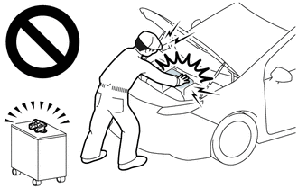
After removing the EV battery service plug grip and FC converter power outlet cable on FC converter side, store them according to the following guidelines to prevent other technicians from accidentally reconnecting them while work is being performed on the high voltage systems.
-The technician performing the work should put the EV battery service plug grip in their pocket and carry it with them.
-Remove the FC converter power outlet cable on FC converter side with a "HIGH-VOLTAGE, DO NOT TOUCH" caution tag attached to it for other technicians.
·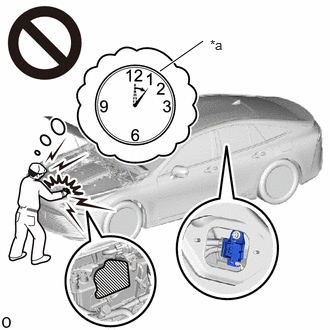 1.667,0.74 2.115,0.427 true 2.188,0.385 2.448,0.552 0.26,0.167 10 false *a
*a Without waiting for 10 minutes
After removing the EV battery service plug grip and FC converter power outlet cable on FC converter side, wait for at least 10 minutes before touching any of the high-voltage connectors or terminals. After waiting for 10 minutes, check the voltage at the terminals in the inspection point in the inverter with converter assembly. The voltage should be 0 V before beginning work.
Click hereEngine / Hybrid System>HYBRID / BATTERY CONTROL>HYBRID CONTROL SYSTEM>PRECAUTION
- HINT:
-
Waiting for at least 10 minutes is required to discharge the high-voltage capacitor inside the inverter with converter assembly and the FC converter assembly.
·Make sure to insulate the high-voltage connectors and terminals of the EV supply battery assembly with insulating tape after removing it.
If the EV supply battery assembly stored without insulating the connectors and terminals, electric shock or fire may result.
·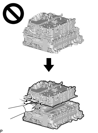
Since high voltage accumulates within the FC stack assembly with FC converter, never perform the work of separating the FC stack assembly with FC converter into the FC converter assembly and FC stack assembly without first performing electrical charge discharge (forced electrical charge discharge or electrical charge self-discharge), because doing so is dangerous.
Click hereEngine / Hybrid System>FC CONTROL>FC STACK>REMOVAL
·Removing and installing the FC stack assembly without first discharging the electrical charge may result in an electric shock due to the high voltage circuit.
- NOTICE:
- ·
After turning the ignition switch off, there may be a waiting time before disconnecting the auxiliary negative (-) battery terminal.
Click hereGeneral>SETUP>WHEN DISCONNECTING OR RECONNECTING BATTERY TERMINAL>BEFORE DISCONNECTING BATTERY
·When disconnecting and reconnecting the auxiliary battery.
Click hereGeneral>SETUP>WHEN DISCONNECTING OR RECONNECTING BATTERY TERMINAL>WORK PROCEDURE
- HINT:
-
When disconnecting and reconnecting the auxiliary battery, there is an automatic learning function that completes learning when the respective system is used.
-
Click hereGeneral>SETUP>WHEN DISCONNECTING OR RECONNECTING BATTERY TERMINAL>AUTOMATIC LEARNING CHART
·This vehicle performs FC system shutdown process after turning the ignition switch off from ON (READY). Therefore, after the ignition switch is turned off from ON (READY), do not perform any work on the electrical system for at least 10 minutes including removing connectors or disconnecting the negative (-) auxiliary battery terminal.
·When the EV control ECU determines that the temperature of FC system components is below 0°C (32°F) when the vehicle is parked with the ignition switch off, it operates the FC air compressor, hydrogen pump and FC cooling water pump for a maximum of 180 seconds to drain the FC stack assembly. When performing inspection or repairs with the ignition switch off (not ON or ON (READY)), disconnect the cable from the negative (-) auxiliary battery terminal before performing work. (If the auxiliary battery voltage is needed to conduct inspection, perform the inspection in an environment with an ambient temperature of 10°C (50°F) or higher.)
PROCEDURE
Pre-procedure1
None.
Procedure1
Check for DTCs.
- Powertrain > EV > Trouble Codes
- 50001 397
- Powertrain > FCDC > Trouble Codes
- 50001 493
- Result:
Result Proceed to Only P1E1500 is output A Any hybrid control system DTCs in the table below are output B Any FC control system DTCs in the table below are output C
| Malfunction Content | System | Relevant DTC | |
|---|---|---|---|
| Micro computer malfunction | Hybrid control system | P060647 | Hybrid/EV Powertrain Control Module Processor Watchdog / Safety MCU Failure |
| P060687 | Hybrid/EV Powertrain Control Module Processor to Monitoring Processor Missing Message | ||
| P060A47 | Hybrid/EV Powertrain Control Module Monitoring Processor Watchdog / Safety MCU Failure | ||
| P060A87 | Hybrid/EV Powertrain Control Module Processor from Monitoring Processor Missing Message | ||
| P060B49 | Hybrid/EV Powertrain Control Module A/D Processing Internal Electronic Failure | ||
| P060B71 | Hybrid/EV Powertrain Control Module A/D Processing Actuator Stuck | ||
| P060B1C | Sensor Power Supply "A" Circuit/Open Circuit Voltage Out of Range | ||
| P0A1B49 | Drive Motor "A" Control Module Internal Electronic Failure | ||
| P1C9E9F | Hybrid/EV System Reset Stuck Off | ||
| P0A1B1F | Drive Motor "A" Control Module Circuit Intermittent | ||
| P1CB038 | Drive Motor "A" Position Sensor REF Signal Frequency Incorrect | ||
| P1C2B00 | Drive Motor "A" Control Module A/D Processing Performance | ||
| P0A1B04 | Drive Motor "A" Control Module System Internal Failure | ||
| P1CA700 | Drive Motor "A" Control Module RAM/ROM Error | ||
| P1CAD49 | Drive Motor "A" Position Sensor Internal Electronic Failure | ||
| P1D0400 | FC Air Compressor Motor Control Module A/D Processing Performance | ||
| P1D0500 | FC Air Compressor Motor Control Module RAM/ROM Error | ||
| P1D8F04 | FC Air Compressor Motor Control Module System Internal Failure | ||
| P1D8F47 | FC Air Compressor Motor Control Module Watchdog/Safety MCU Failure | ||
| P1D8F49 | FC Air Compressor Motor Control Module Internal Electronic Failure | ||
| P1E8649 | FC Air Compressor Motor Position Sensor Internal Electronic Failure | ||
| P1C731C | Sensor Reference Voltage "H" Circuit/Open Circuit Voltage Out of Range | ||
| P1E3B87 | Communication Error from FC Air Compressor Motor to Drive Motor "A" Missing Message | ||
| FC control system | P060B16 | Internal Control Module A/D Processing Performance Circuit Voltage Below Threshold | |
| Power source circuit malfunction | Hybrid control system | P06D61C | Sensor Reference Voltage "F" Circuit/Open Circuit Voltage Out of Range |
| P06B01C | Sensor Power Supply "A" Circuit/Open Circuit Voltage Out of Range | ||
| P06E61C | Sensor Power Supply "C" Circuit/Open Circuit Voltage Out of Range | ||
| FC control system | P1F451F | FC Converter Control Module Power Relay Sense Circuit Intermittent | |
| P1F651C | FC Converter Control Module Power Supply (-5V) Circuit Voltage Out of Range | ||
| P1F661C | FC Converter Control Module Power Supply (+V5AREF) Circuit Voltage Out of Range | ||
| Communication system malfunction | Hybrid control system | P312387 | Lost Communication with Drive Motor Control Module "A" from Hybrid/EV Control Module Missing Message |
| FC control system | U029387 | Lost Communication with Hybrid/EV Powertrain Control Module Missing Message | |
| U116087 | Lost Communication with FCDC Control Module Missing Message | ||
| Sensor and actuator circuit malfunction | Hybrid control system | P0A3F16 | Drive Motor "A" Position Sensor Circuit Voltage Below Threshold |
| P0A1B00 | Drive Motor "A" Control Module Performance | ||
| P1CB038 | Drive Motor "A" Position Sensor REF Signal Frequency Incorrect | ||
| P1CB300 | Drive Motor "A" Position Sensor REF Signal Oscillation Stop | ||
| P0A3F16 | Drive Motor "A" Position Sensor Circuit Voltage Below Threshold | ||
| P0A3F22 | Drive Motor "A" Position Sensor Signal Amplitude > Maximum | ||
| P1D8F00 | FC Air Compressor Motor Control Module Performance | ||
| P1E8800 | FC Air Compressor Motor Position Sensor REF Signal Oscillation Stop | ||
| P1D7516 | FC Air Compressor Motor Position Sensor Circuit Voltage Below Threshold | ||
| P1D7522 | FC Air Compressor Motor Position Sensor Signal Amplitude > Maximum | ||
| P1D751C | FC Air Compressor Motor Position Sensor Circuit Voltage Out of Range | ||
| FC control system | P1D1C16 | FC Converter Output Voltage Sensor Circuit Voltage Below Threshold | |
| P1D1C17 | FC Converter Output Voltage Sensor Circuit Voltage Above Threshold | ||
| P1D2017 | FC Converter Input Voltage Sensor Circuit Voltage Above Threshold | ||
| P1E8783 | FC Air Compressor Motor Position Sensor REF Signal Frequency Incorrect | ||
| P1E9011 | FC Positive Contactor Control Circuit Short to Ground | ||
| P1E9015 | FC Positive Contactor Control Circuit Short to Battery or Open | ||
| P1E9211 | FC Precharge Contactor Control Circuit Short to Ground | ||
| P1E9215 | FC Precharge Contactor Control Circuit Short to Battery or Open | ||
| P1E9111 | FC Negative Contactor Control Circuit Short to Ground | ||
| P1E9115 | FC Negative Contactor Control Circuit Short to Battery or Open | ||
| P1F009E | FC Converter Overvoltage Signal Stuck On | ||
| System malfunction | Hybrid control system | P0D2D1C | Drive Motor "A" Inverter Voltage Sensor Voltage Out of Range |
| P1C8349 | High Voltage Power Resource Circuit Voltage Sensor after Boosting Malfunction | ||
| P0C7600 | Hybrid/EV Battery System Discharge Time Too Long | ||
| P0D2D16 | Drive Motor "A" Inverter Voltage Sensor "A" Circuit Voltage Below Threshold | ||
| P0D2D17 | Drive Motor "A" Inverter Voltage Sensor "A" Circuit Voltage Above Threshold | ||
| P1CB69E | Drive Motor "A" Inverter Voltage Sensor(VH) Stuck On | ||
| FC control system | P1D0E62 | Inverter Output Voltage/FC Converter Output Voltage Signal Compare Failure | |
Post-procedure1
Turn the ignition switch off.
A
B
C
Click hereEngine / Hybrid System>HYBRID / BATTERY CONTROL>HYBRID CONTROL SYSTEM>P056014
- Result:
Proceed to OK NG
OK
NG
Click hereEngine / Hybrid System>FC CONTROL>FC CONTROL SYSTEM>P1D0619
- Result:
Result Proceed to OK A NG (The connector is not connected securely.) B NG (The terminals are not making secure contact or are deformed, or water or foreign matter exists in the connector.) C
A
B
C
- CAUTION:
-
Be sure to wear insulated gloves.
Pre-procedure1
Check that the service plug grip and FC converter power outlet cable are not installed.
- NOTICE:
-
After removing the service plug grip and FC converter power outlet cable, do not turn the ignition switch to ON (READY), unless instructed by the repair manual because this may cause a malfunction.
Remove the electric heater sub-assembly.
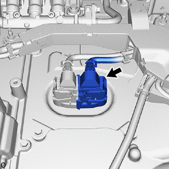
Disconnect the B19 FC converter assembly connector.
Disconnect the A16 EV Control ECU connector.
Procedure1
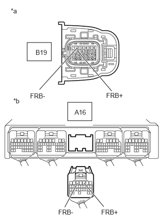
| *a | front view of wire harness connector
(to FC Converter Assembly) |
| *b | Rear view of wire harness connector
(to EV Control ECU) |
Measure the resistance according to the value(s) in the table below.
- Standard Resistance:
Tester Connection Condition Specified Condition Click Location & Routing(A16,B19)Location & Routingewd_type=routing;type=c,c;code=A16,B19
Click Connector(A16)Instrument Panel>Front Compartment Main Wire>EV Control ECUewd_type=component;type=c;code=A16;pinno=3,5
Click Connector(B19)Engine Compartment>No. 2 Stack Wire>FC Converter Assemblyewd_type=component;type=c;code=B19;pinno=8,2
A16-3 (FRB+) - B19-8 (FRB+) Ignition switch off Below 1 Ω A16-5 (FRB-) - B19-2 (FRB-) Ignition switch off Below 1 Ω A16-3 (FRB+) or B19-8 (FRB+) - Body ground and other terminals Ignition switch off 10 kΩ or higher A16-5 (FRB-) or B19-2 (FRB-) - Body ground and other terminals Ignition switch off 10 kΩ or higher
- Result:
Proceed to OK NG
Post-procedure1
Reconnect the A16 EV Control ECU connector.
Reconnect the B19 FC converter assembly connector.
Install the electric heater sub-assembly.
OK
NG
Pre-procedure1
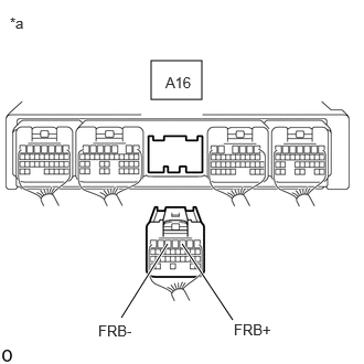
| *a | Rear view of wire harness connector
(to EV Control ECU) |
Disconnect the A16 EV Control ECU connector.
Procedure1
Measure the resistance according to the value(s) in the table below.
- Standard Resistance:
Tester Connection Condition Specified Condition Click Location & Routing(A16)Location & Routingewd_type=routing;type=c;code=A16
Click Connector(A16)Instrument Panel>Front Compartment Main Wire>EV Control ECUewd_type=component;type=c;code=A16;pinno=3,5
A16-3 (FRB+) - A16-5 (FRB-) Ignition switch off 11.07 to 13.53 Ω
- Result:
Proceed to OK NG
Post-procedure1
Reconnect the A16 EV control ECU connector.
OK
NG
- HINT:
-
Click hereEngine / Hybrid System>FC CONTROL>CONVERTER ASSEMBLY>REMOVAL
- Result:
Proceed to NEXT
NEXT
Replace the FC converter assembly components listed below.
Click hereEngine / Hybrid System>FC CONTROL>CONVERTER ASSEMBLY>DISASSEMBLY
FC stack main relay (FRB)
FCDC converter control ECU board sub-assembly
No. 1 FC converter wire
No. 2 FC converter wire
FC converter power module transistor
- HINT:
- ·
Refer to the parts location for the FC converter assembly components.
Click hereEngine / Hybrid System>HYBRID / BATTERY CONTROL>HYBRID CONTROL SYSTEM>PARTS LOCATION
·Refer to the system description for the parts location of the FC converter assembly components.
Click hereEngine / Hybrid System>HYBRID / BATTERY CONTROL>HYBRID CONTROL SYSTEM>SYSTEM DESCRIPTION